
Double-winding permanent magnet motor

A permanent magnet motor and double-winding technology, which is applied in the direction of motors, windings, synchronous motors with rotating armatures and stationary magnets, etc., can solve the problems of difficult to meet the acceleration requirements of vehicle starting, the reduction of motor starting torque, and the difficulty of high-speed motors Operation and other problems, to achieve good regenerative braking effect, strong overload capacity, and reduce the burden of mechanical brakes

Inactive Publication Date: 2010-12-01
马善振
View PDF5 Cites 12 Cited by
  • Summary
  • Abstract
  • Description
  • Claims
  • Application Information

AI Technical Summary

Problems solved by technology

At present, the permanent magnet motors used in electric vehicles all use single-winding motors. If this kind of motor is required to have a large starting torque during design and manufacture, it is difficult for the motor to achieve high-speed operation due to the limitation of the back-emf coefficient, or it can only be controlled by complex field weakening. To achieve high speed, the weak field control consumes battery energy; on the contrary, if the motor is designed to a higher speed, the starting torque of the motor will be reduced, it is difficult to meet the vehicle starting acceleration requirements, or it can only be achieved by increasing the motor winding current to increase the starting torque

Method used


Image

  • Double-winding permanent magnet motor
  • Double-winding permanent magnet motor
  • Double-winding permanent magnet motor

Examples


Embodiment Construction

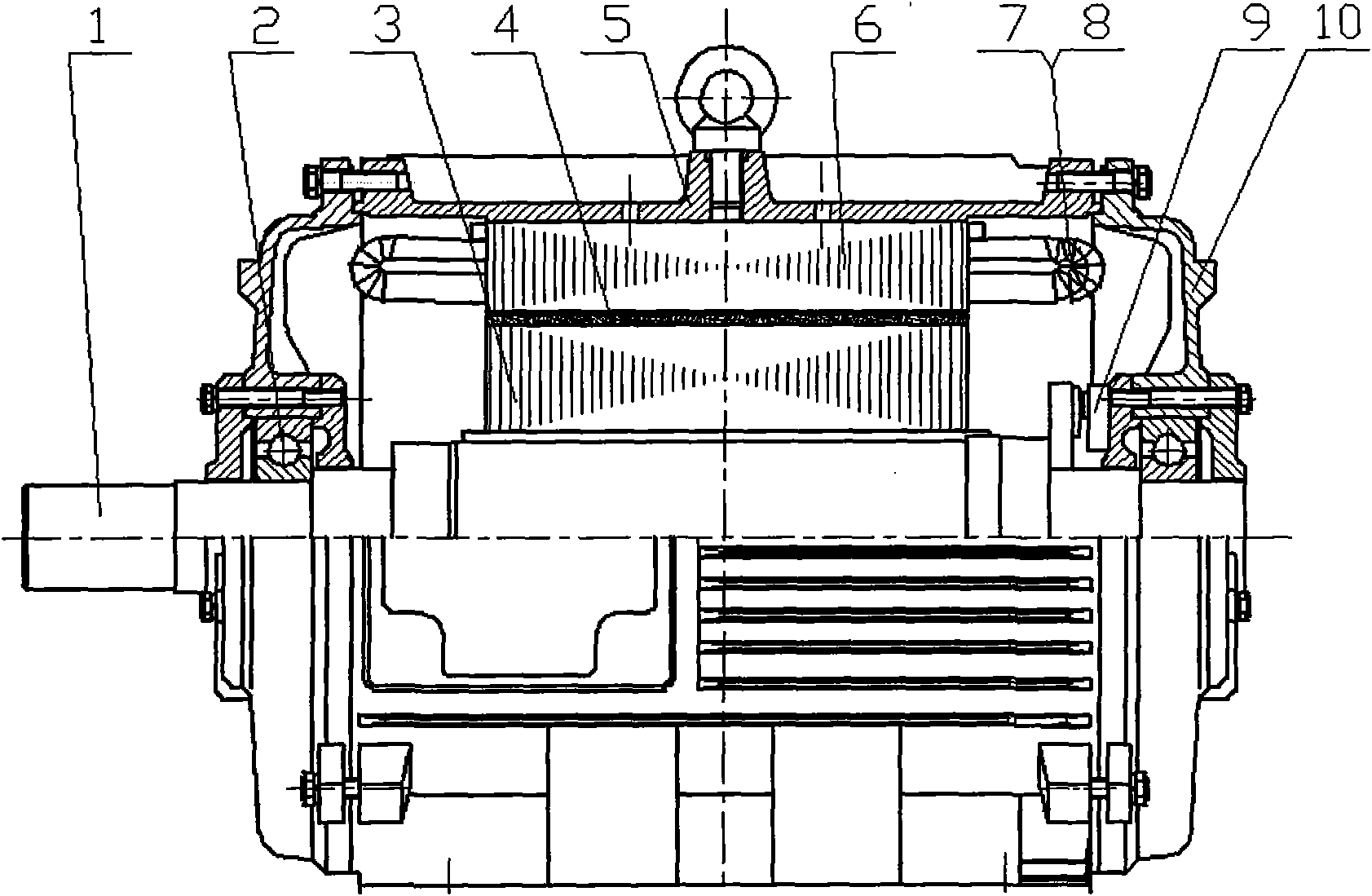
[0010] Such as figure 1 As shown, the rotor core 3 is stacked as a whole and then press-fitted on the motor shaft 1, the magnetic steel 4 is pasted on the rotor core 3, the bearing 2 is mounted on the motor shaft 1, and the stator core 6 is press-fitted on the stator casing 5 Inside, the high-torque winding 7 and the high-speed winding 8 are installed in the slot of the stator core 6, the outer end of the motor end cover 10 is connected with the stator casing 5, and the inner end is connected with the outer ring of the bearing 2, so that the motor becomes a Overall, the rotating part of the position detection device 9 is mounted on the motor shaft 1 , and the stationary part of the position detection device 9 is mounted on the motor end cover 10 .

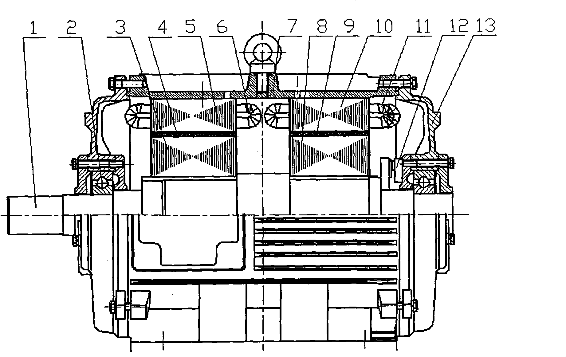
[0011] Another structural form of the present invention is as figure 2 As shown, the motor consists of two sets of stator and rotor cores, independent high-torque windings 7, high-speed windings 8 and related components, high-tor...


PUM


Abstract

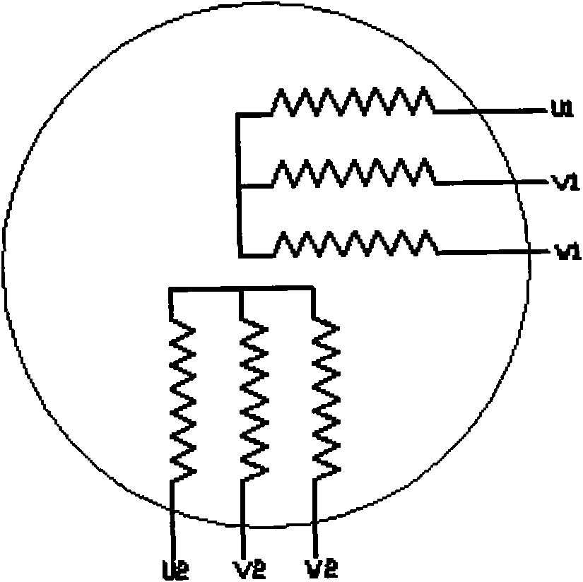
The invention discloses a double-winding permanent magnet motor, which consists of a rotor part, a stator part and a position detection part, wherein the rotor part consists of a motor shaft, a rotor core, a magnetic steel, a bearing and the like; and the stator part mainly comprises a stator shell, a stator core, a large-torque winding, a high-speed winding, an end cover and the like. Compared with the conventional product, the load property of the double-winding permanent magnet motor is very accordant with that of an electric vehicle; when the vehicle is started or climbs a slope, the large-torque winding of the motor works, and the motor outputs a large torque; and when the vehicle needs to run at a high speed, the high-speed winding of the motor works, and the motor can provide a high rotational speed to drive the vehicle to run at the high speed. The double-winding permanent magnet motor has the characteristics of wide speed range, large low-speed motor torque, good high-speed performance, high efficiency, good regenerative braking effect, small volume, light weight, high specific power, high reliability and relatively simple control system thereof, and is an ideal driving motor of the electric vehicle.

Description

Technical field [0001] The invention relates to a motor, in particular to a double-winding permanent magnet motor. Background technique [0002] At present, the three core technologies of electric vehicles are battery, motor and electronic control. The main difficulties lie in the small capacity of the battery and the small number of charge and discharge times, which lead to two main points of electric vehicle technology: one is the insurmountable bottleneck of battery technology, How to improve the efficiency of electric energy use and increase the mileage of electric vehicles requires that the driving motor must conform to the characteristics of the battery, that is, the selected motor must have high efficiency, low current, avoid instantaneous large current discharge of the battery, and have good energy feedback performance of the motor. Second, restricted by battery performance, electric vehicles are mainly used in urban traffic, and the vehicle is in the working state o...

Claims


Application Information

Patent Timeline
Patent Type & Authority Applications(China)
IPC IPC(8): H02K3/00H02K16/00H02K21/26H02K29/00
CPCY02T10/641Y02T10/64
Inventor 马善振
Owner 马善振
Learn More