
Imaging velocity analysis method of seismic scattering P-P waves

A technology of imaging velocity and seismic scattering, applied in the direction of seismic signal processing, etc., can solve the problem of increasing computing cost, achieve the effect of strong focusing ability, improve signal-to-noise ratio, and reduce the influence of multiple waves

Inactive Publication Date: 2010-12-01
XI'AN PETROLEUM UNIVERSITY
View PDF8 Cites 14 Cited by
  • Summary
  • Abstract
  • Description
  • Claims
  • Application Information

AI Technical Summary

Problems solved by technology

Subsequently, on the basis of reflection theory, post-stack migration imaging technology and pre-stack partial migration + post-stack migration technology were developed. There is a strange circle of disadvantages in the reflected wave component; followed by the development of prestack migration imaging technology, to some extent, it is an imaging technology at the cost of increasing the calculation cost. The velocity model is still the key to this imaging technology, although the corrected The method of velocity model weakens the disadvantages of obtaining the initial velocity model based on CMP gather processing, but the problem of how to correct the velocity model to obtain the correct imaging is in front of us, because the unknown underground geological conditions are exactly what we want to obtain by processing seismic data. That is, the velocity model is not known in advance, and the accuracy of velocity model correction is directly related to the effect of seismic wave imaging, so the prestack migration imaging technology still jumps into a vicious circle of how to correct the velocity model and accurate seismic wave imaging

Method used


Image

  • Imaging velocity analysis method of seismic scattering P-P waves
  • Imaging velocity analysis method of seismic scattering P-P waves
  • Imaging velocity analysis method of seismic scattering P-P waves

Examples


Embodiment 1

[0060] Take a fault model seismic data containing 51 shots, 64 traces per shot, and 1024 sampling points per trace as an example to illustrate the implementation steps of this example:

[0061] Step 1: Read the seismic data containing 51 shots, 64 traces per shot, and 1024 sampling points per trace into the two-dimensional array F, and load the observation system parameters into the original seismic data trace header, and according to the observation system and acquisition parameters to calculate the location and coordinates of scattering points;

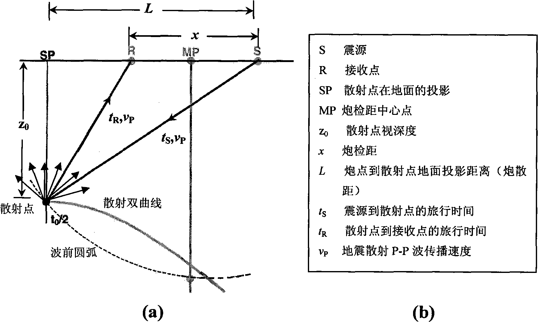
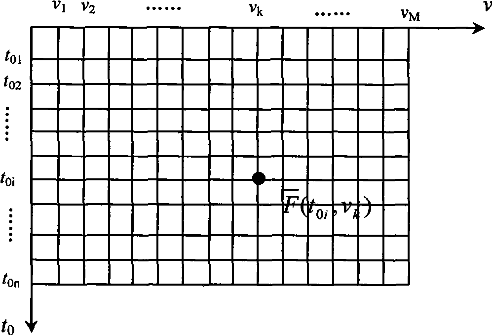
[0062] Step 2: According to the time-distance hyperbolic equation of the scattered wave, on the shot set, fix t 0i In the case of , choose a velocity v arbitrarily k , the speed can determine a hyperbolic trajectory, and superimpose or correlate the scattering amplitudes at each offset along the hyperbolic trajectory, and then weight and sum the energy of the same scattering point to obtain the corresponding average amplitude;

[...

Embodiment 2

[0067] Take an actual exploration seismic data containing 161 shots, 240 traces per shot, and 2000 sampling points per trace as an example to illustrate the implementation steps of this example:

[0068] Step 1: Read the seismic data containing 161 shots, 240 traces per shot, and 2,000 sampling points per trace into the two-dimensional array F, and load the observation system parameters into the original seismic data header, and according to the observation system and acquisition parameters to calculate the location and coordinates of scattering points;

[0069] Step 2: According to the time-distance hyperbolic equation of the scattered wave, on the shot set, fix t 0i In the case of , choose a speed v arbitrarily k , the speed can determine a hyperbolic trajectory, and superimpose or correlate the scattering amplitudes at each offset along the hyperbolic trajectory, and then weight and sum the energy of the same scattering point to obtain the corresponding average amplitude; ...


PUM


Abstract

The invention relates to an imaging velocity analysis method of seismic scattering P-P waves. The method comprises the following steps of: (1) reading seismic data into a two-dimensional array F, meanwhile, loading a parameter of an observation system into a trace header of original seismic data, and working out the position and coordinates of a scattering point according to the observation system and an acquired parameter; (2) randomly selecting a velocity vk on a shot set according to a scattered wave time-distance hyperbolic equation under the condition of fixed t0i, wherein the velocity can be used for determining a hyperbolic trace, and scattering amplitudes on all shot-geophone distances are superposed or correlated along the hyperbolic trace; then weighting and summating energies of the same scattering point to obtain a corresponding average amplitude; (3) manufacturing a velocity spectrum, wherein a series of vertical two-way travel time is firstly selected. The invention has the characteristics of increasing the superposition numbers of times of the velocity analysis technology, effectively improving the signal to noise ratio and more precisely obtaining the imaging velocity.

Description

technical field [0001] The invention belongs to the technical field of seismic wave velocity parameter extraction and imaging processing, in particular to a seismic scattering P-P wave imaging velocity analysis method. technical background [0002] Velocity is the basis of seismic wave propagation and one of the key factors in imaging. The accuracy of velocity acquisition is directly related to the accuracy of seismic wave imaging. The starting point of velocity acquisition of traditional seismic wave imaging technology is derived from the reflected wave time-distance equation velocity analysis technology, which is the root of the disadvantages of traditional seismic wave imaging technology. The reflection wave is very limited in the seismic wave component, and the propagation law of the reflection wave is different from other components of the seismic wave. If the other components of the seismic wave are treated with the reflection theory, the velocity parameters obtained m...

Claims


Application Information

Patent Timeline
IPC IPC(8): G01V1/30
Inventor 沈鸿雁
Owner XI'AN PETROLEUM UNIVERSITY
Learn More