


Quick Research
Generate reliable direction feasibility study reports for your R&D in just a few steps.

Technical Q&A
Discover and master advanced knowledge NOW. Basics, ideas, possibilities, all at once.

Find Solutions
As an expert in R&D theories, this can generate solutions to your technical problems instantly.

Evaluate Feasibility
Analyze your overall solution with one click, know your potential R&D risks in advance.

Monitor Landscape
Get weekly tech updates, stay abreast of the latest tech innovations and key insights.
Rotation angle sensor
A rotation angle and sensor technology, which is applied to instruments, uses electric/magnetic devices to transmit the direction of sensing components, measuring devices, etc., can solve the problems of complicated assembly process of the rotation angle sensor, and achieves easy wiring connection, easy assembly of parts, The effect of high magnetic shielding effect
- Summary
- Abstract
- Description
- Claims
- Application Information
AI Technical Summary
Problems solved by technology
Method used
Image

Examples
Embodiment Construction
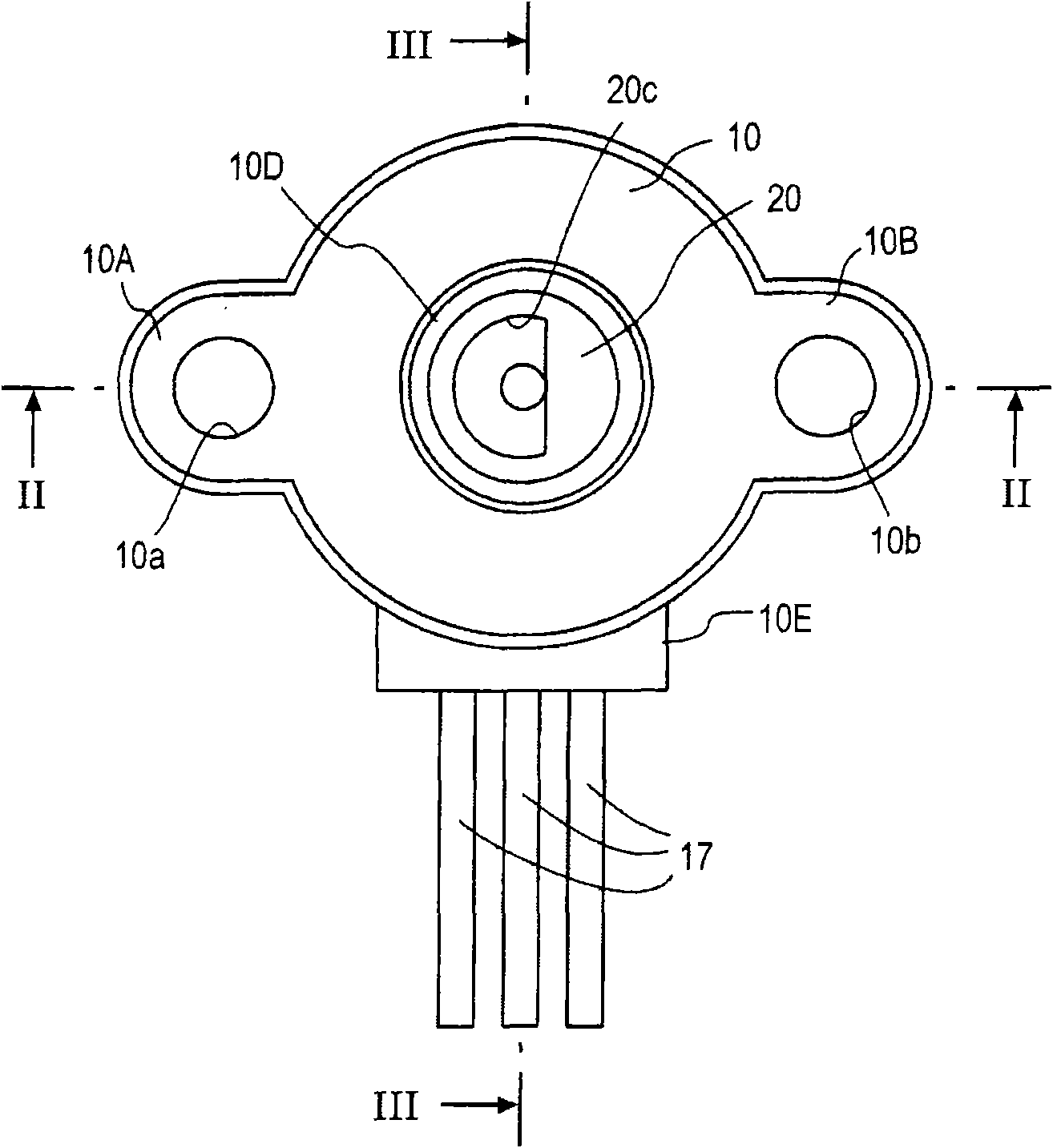
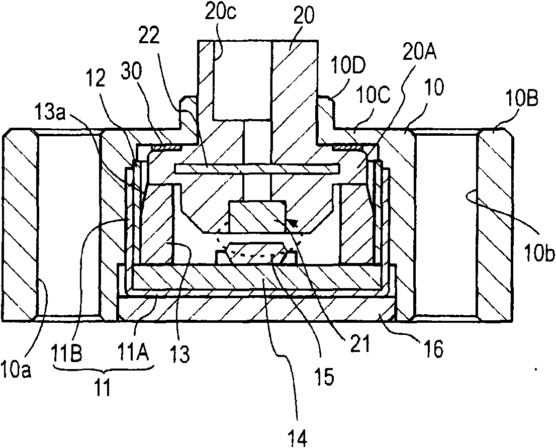
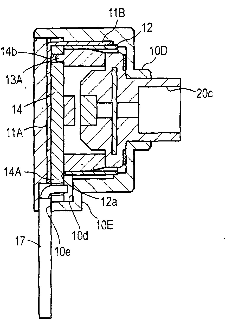
[0018] figure 1 Represent the top view of the first embodiment of the rotation angle sensor of the present invention, figure 2 and image 3 Respectively figure 1 The II-II section and III-III section. The rotation angle sensor includes: a casing 10 formed of a substantially cylindrical insulator having mounting protrusions 10A, 10B on both sides, a rotor 20 fitted in the casing 10 with one end protruding outward, and a casing fixed to the rotor 20 The magnet 21 at the other end in the body 10, the ring bearing 13 that is installed in the housing 10 and receives the inner end of the rotor 20 from one end, the wiring board 14 that supports the other end of the ring bearing 13, and the inside of the ring bearing 13. The rotor 20 is opposed to the magnet 21 in the axial direction with a magnetic sensor IC (integrated circuit) 15 mounted on the wiring board 14, a cylindrical magnetic shield 12 surrounding the ring bearing 13, and the wiring board. 14 and the cylindrical magn...
PUM
 Abstract
Description
Claims
Application Information
 - R&D Engineer
- R&D Manager
- IP Professional
- Industry Leading Data Capabilities
- Powerful AI technology
- Patent DNA Extraction
Browse by: Latest US Patents, China's latest patents, Technical Efficacy Thesaurus, Application Domain, Technology Topic, Popular Technical Reports.
© 2024 PatSnap. All rights reserved.Legal|Privacy policy|Modern Slavery Act Transparency Statement|Sitemap|About US| Contact US: help@patsnap.com