Eureka AIR delivers breakthrough ideas for toughest innovation challenges, trusted by R&D personnel around the world.

Road finisher and method

A technology of road paver and internal combustion engine, which is applied in the direction of roads, roads, road repair, etc., can solve the problems of high fuel consumption, pollute the environment, low efficiency, etc., and achieve the effect of high transportation speed and easy starting.

Active Publication Date: 2010-12-01
JOSEPH VOEGELE AG
View PDF7 Cites 2 Cited by
  • Summary
  • Abstract
  • Description
  • Claims
  • Application Information

AI Technical Summary

Problems solved by technology

Subsequent operation of the internal combustion engine while its efficiency against significant but unnecessary drag loads is rather low, pollutes the environment, leads to high fuel consumption and increases the frequency of repairs of the hydraulic system and permanently operating functional units due to increased wear

Method used


Image

  • Road finisher and method
  • Road finisher and method
  • Road finisher and method

Examples


Embodiment Construction

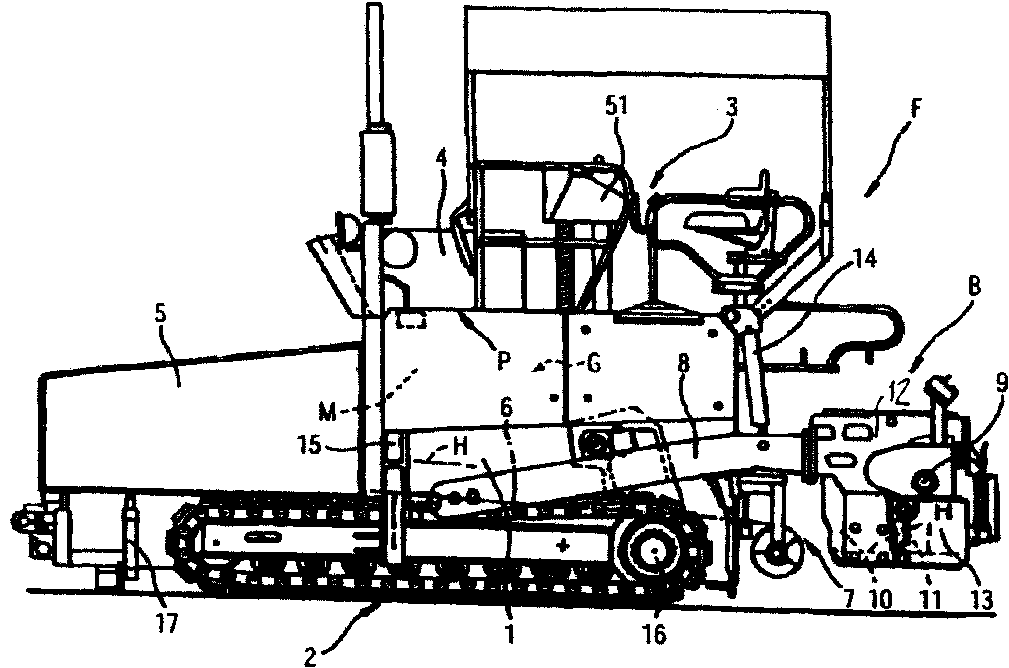
[0023] Self-propelled paving machine F ( figure 1 ) can also travel at significantly higher transport travel speeds. The paving machine F has a traveling frame 2 on a chassis 1 . The frame 2 shown is a tracked frame. Alternatively a wheeled carriage (not shown) may be provided. The traveling frame 2 is driven by at least one hydraulic drive motor 16 . A hopper 5 for paving material is arranged in the front area of ​​the chassis 1 . The longitudinal conveying means 6 extend within and through the chassis 1 to a transverse distribution assembly 17 arranged at the rear end of the chassis 1 . The lateral distribution assembly 17 is typically a hydraulically driven lateral distribution auger. The longitudinal conveying device 6 can be driven, for example, by a hydraulic motor not shown, and can even include an electric heating device H. The transverse distribution assembly 17 is arranged in front of the paving screed B which is drawn by the paving machine F on the drawbar 8 ....


PUM


Abstract

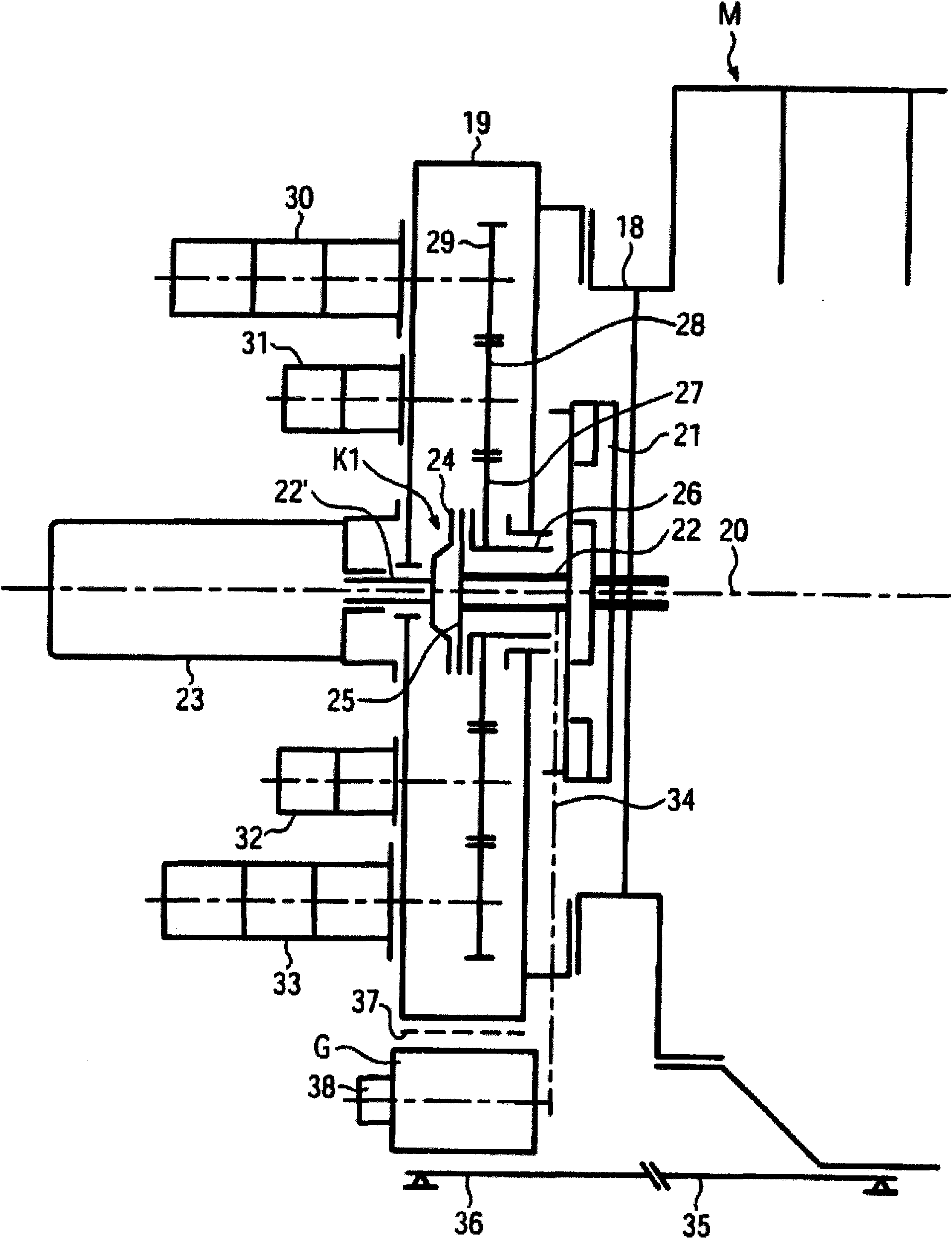
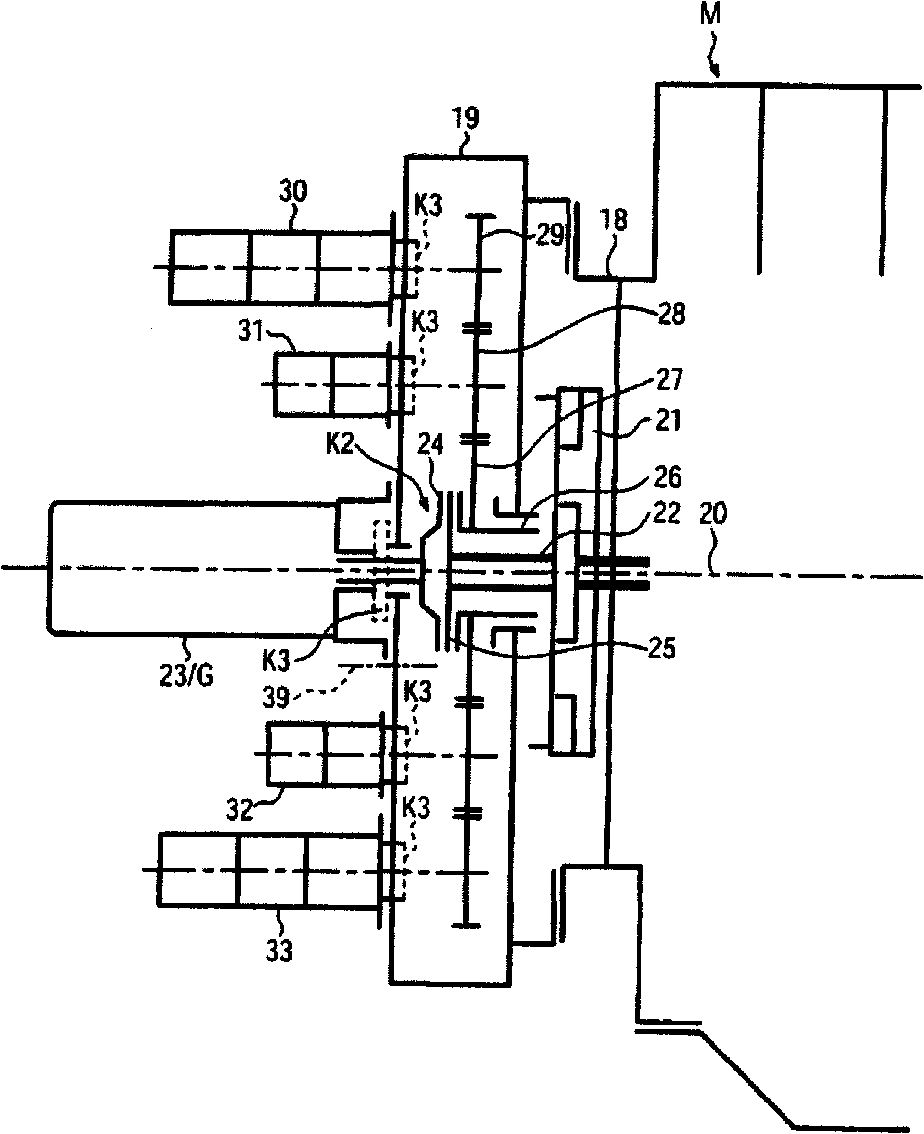
In a paver F comprising a combustion engine M, in particular a diesel engine, of a primary driving aggregate P, functional units having hydraulic pumps 23, 30 to 33 inclusive a travel pump aggregate 23 which can be driven by the combustion engine M for supplying at least one travel drive 16, a generator G for supplying electric heating devices H of the paver F and / or of a paving screed B of the paver F with electric power, the generator G is driven permanently while at least one pump 23, 30 to 33 selectively can be disconnected from the combustion engine via at least one shiftable clutch K1, K2, K3. During a heating-up phase of electric heating devices H via the permanently driven generator G at least one of the pumps is disconnected. During transport travel at least one pump of the functional units, except the permanently driven travel pump aggregate 23 and the generator G, is disconnected. During start and, optionally, during warm-up of the combustion engine M pumps of functional units, optionally including the travel pump aggregate 23, are disconnected.

Description

technical field [0001] The invention relates to a paving machine according to the preamble of claim 1 and a method according to the preamble of claims 9 , 10 , 11 . Background technique [0002] Paving machines (EP 1118714A, EP0489969A, DE 10300745A1) including heating means or high-efficiency electric motors supplied with power from a generator, which require at least momentary high power, for example when the paving machine is on a longitudinal conveyor or the paving screed of the paving machine is used for tamping Devices, pressure rods, bottom plates, etc. The internal combustion engine drives via the pump power take-off several hydraulic pumps including the traveling pump combination, all hydraulic pumps together with corresponding hydraulic motors or hydraulic cylinders distributed on the paving machine and / or paving screed define a power functional unit. All functional units are permanently driven by the crankshaft of the internal combustion engine via a torsionally ...

Claims


Application Information

Patent Timeline
IPC IPC(8): E01C19/12
CPCE01C19/48
Inventor 阿瑟·舍费尔克里斯蒂安·帕夫利克托马斯·施密特
Owner JOSEPH VOEGELE AG
Why Eureka
Eureka Blog
Learn More