
Thread trapper device for a spindle of a spinning or thread machine

A technology of twisting machine and spinning machine, applied in spinning machine, continuous winding spinning machine, transportation and packaging, etc., can solve problems such as vibration insensitivity

Active Publication Date: 2010-12-01
MASCHINENFABRIK RIETER AG
View PDF9 Cites 7 Cited by
  • Summary
  • Abstract
  • Description
  • Claims
  • Application Information

AI Technical Summary

Problems solved by technology

Furthermore the magnets are expensive components, especially in the present case they must have a high magnetic force and at the same time must be insensitive to vibrations

Method used


Image

  • Thread trapper device for a spindle of a spinning or thread machine
  • Thread trapper device for a spindle of a spinning or thread machine
  • Thread trapper device for a spindle of a spinning or thread machine

Examples


Embodiment Construction

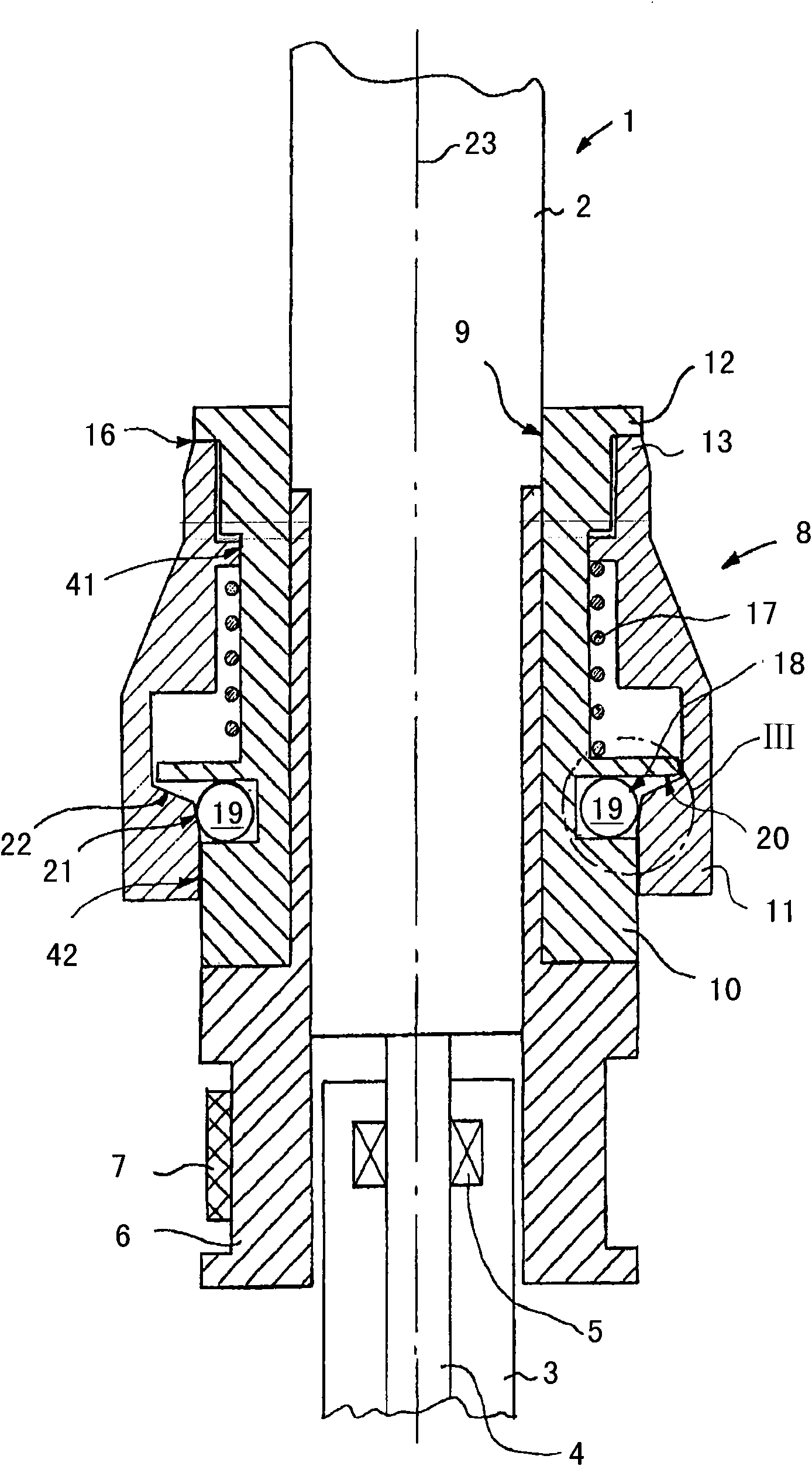
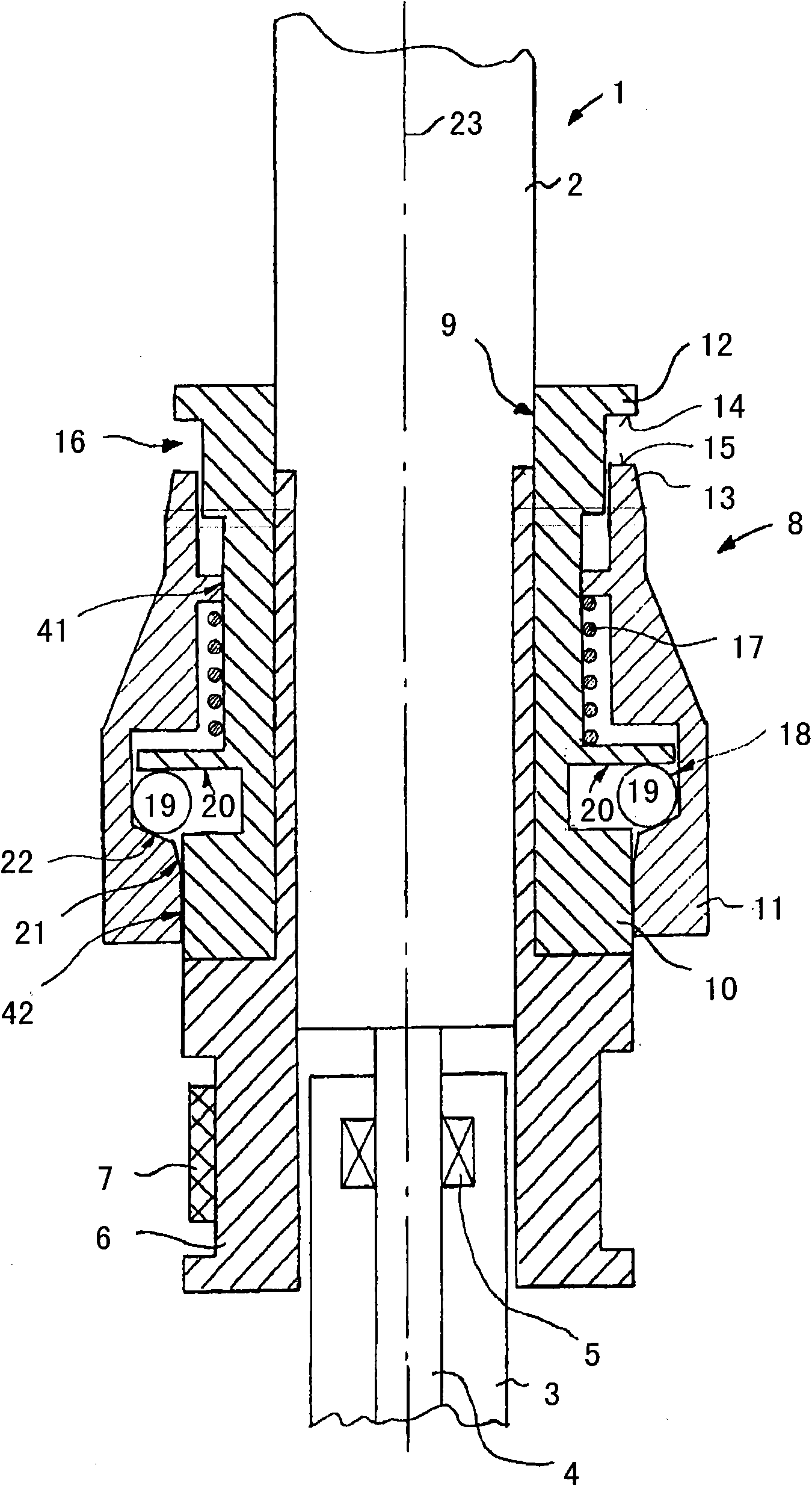
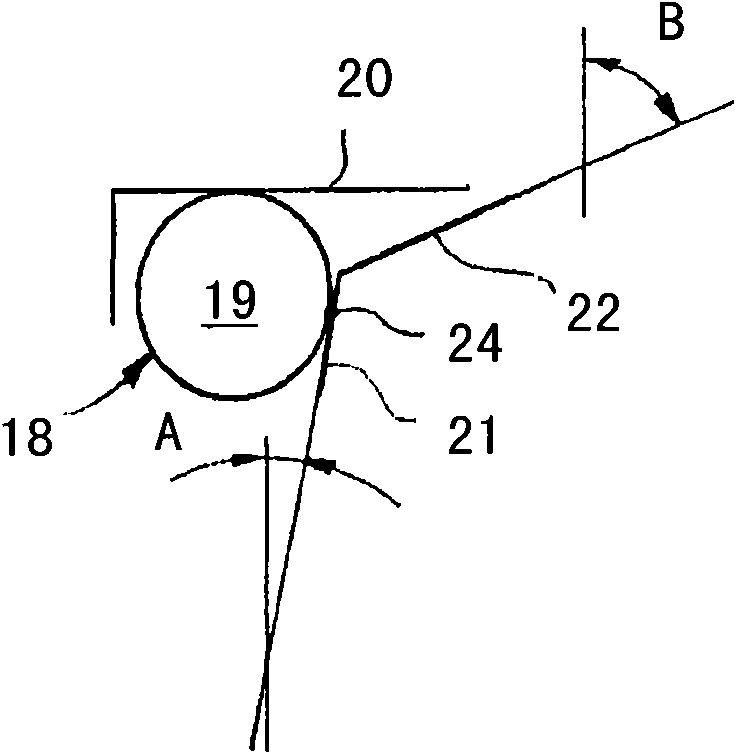
[0023] figure 1 A spindle 1 of a spinning or twisting machine is shown in . The spindle 1 consists of a rotating upper part 2 and a non-rotating bearing housing 3 , which is fixed stationary on a not shown spindle rail. The upper part 2 has a shaft 4 which rotates therewith, which is mounted in a bearing housing 3 in journal bearings 5 ​​and a not shown end bearing. The upper part 2 contains a spindle 6 via which the upper part can be driven with a belt 7 .

[0024]The top of the spindle disk 6 is provided with a clamping device 8 . The yarn clamping device 8 is mounted on the spindle upper part 2 by means of a mounting frame 9 . The clamping device 8 is preferably fastened detachably to the upper part 2 so that it can be easily replaced in case of a problem. Above the yarn clamping device 8, the upper part 2 can accommodate a bobbin, not shown, on which bobbin the produced yarn is wound into yarn bobbins. The winding process is carried out in a known manner with a liftab...


PUM


Abstract

The invention relates to a thread trapper device for a spindle of a spinning or thread machine. The thread trapper device comprises a mounting rack for mounting the thread trapper on a spindle and two retainers capable of mutually oppositely moving and for retaining the thread. At least one loading element uses the loading force to close the retainer and at least one unloading element generates the unloading force opposite to the direction of the loading force. The unloading element moves under centrifugal force with rotating spindle. The retainer is opened by the unloading force. One unloading element is attached at least two positions in the thread trapper such that the different unloading forces are generated at positions during defined spindle speed by the unloading element.

Description

technical field [0001] The invention relates to a yarn clamping device for a spindle of a spinning machine or a twisting machine. The clamping part has at least one loading element that closes the clamping part with a loading force, and has at least one unloading element for generating an unloading force opposite to the direction of the loading force, wherein the unloading element can be placed on the spindle in the clamping device When rotating, it moves under the action of centrifugal force, and the clamp can be opened by unloading force. Background technique [0002] A clamping device of this type is known from the document WO 2007 / 131562 A1. The loading element for clamping the yarn is formed by a spring in known clamping devices. A plurality of relief elements in the form of balls are arranged in the clamping device, which are movable in the radial direction and are guided in guides in the form of half-shells. The guide mechanism of the ball is configured to open and...

Claims


Application Information

Patent Timeline
Patent Type & Authority Applications(China)
IPC IPC(8): D01H1/38D01H1/40D01H7/04
CPCB65H65/00D01H1/38B65H2701/31
Inventor G·斯塔莱克W·佐特N·斯托普
Owner MASCHINENFABRIK RIETER AG
Learn More