
Method for realizing early warning and positioning of malfunctions for power cable network

A technology of fault early warning and implementation method, which is applied in the direction of electrical components, electromagnetic wave transmission systems, transmission systems, etc., can solve the problems of difficult to give early warning information and lack of targeted solutions for optical cable network faults, and achieve enhanced anti-destruction capabilities, Huge economic and social benefits, the effect of reducing losses

Active Publication Date: 2010-11-24
STATE GRID ELECTRIC POWER RES INST
View PDF7 Cites 18 Cited by
  • Summary
  • Abstract
  • Description
  • Claims
  • Application Information

AI Technical Summary

Problems solved by technology

However, the system construction is mainly carried out around static optical cable resource management and optical cable fault location. When an optical cable fault occurs, the optical distance of the fault point is obtained through the system integrated optical fiber monitoring equipment for testing, and the attribute data (optical distance, geographical distance) , disk retention) to calculate the geographic distance, and realize fault location through the geographic information platform of the system, but it is difficult to give early warning information for potential faults in the optical cable network, and there is a lack of targeted solutions

Method used


Image

  • Method for realizing early warning and positioning of malfunctions for power cable network
  • Method for realizing early warning and positioning of malfunctions for power cable network
  • Method for realizing early warning and positioning of malfunctions for power cable network

Examples


Embodiment Construction

[0025] The present invention will be further described below in conjunction with accompanying drawing:

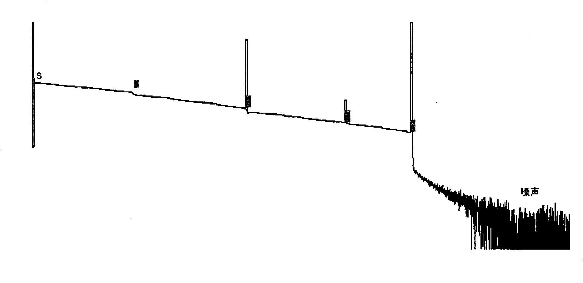
[0026] 1) Start the optical time domain reflectometer OTDR to test the specified optical fiber link, obtain the test data of the optical cable, and draw the optical time domain reflectometer OTDR curve, such as figure 1 .

[0027] 2) Determine the end point of the optical fiber through the noise at the end of the curve, the first reflection point with an upward mutation before the noise, such as figure 1 Point E, point S to point E is the distribution of optical fiber link test data, and after point E is noise data, which does not contain signal data and does not need to be analyzed.

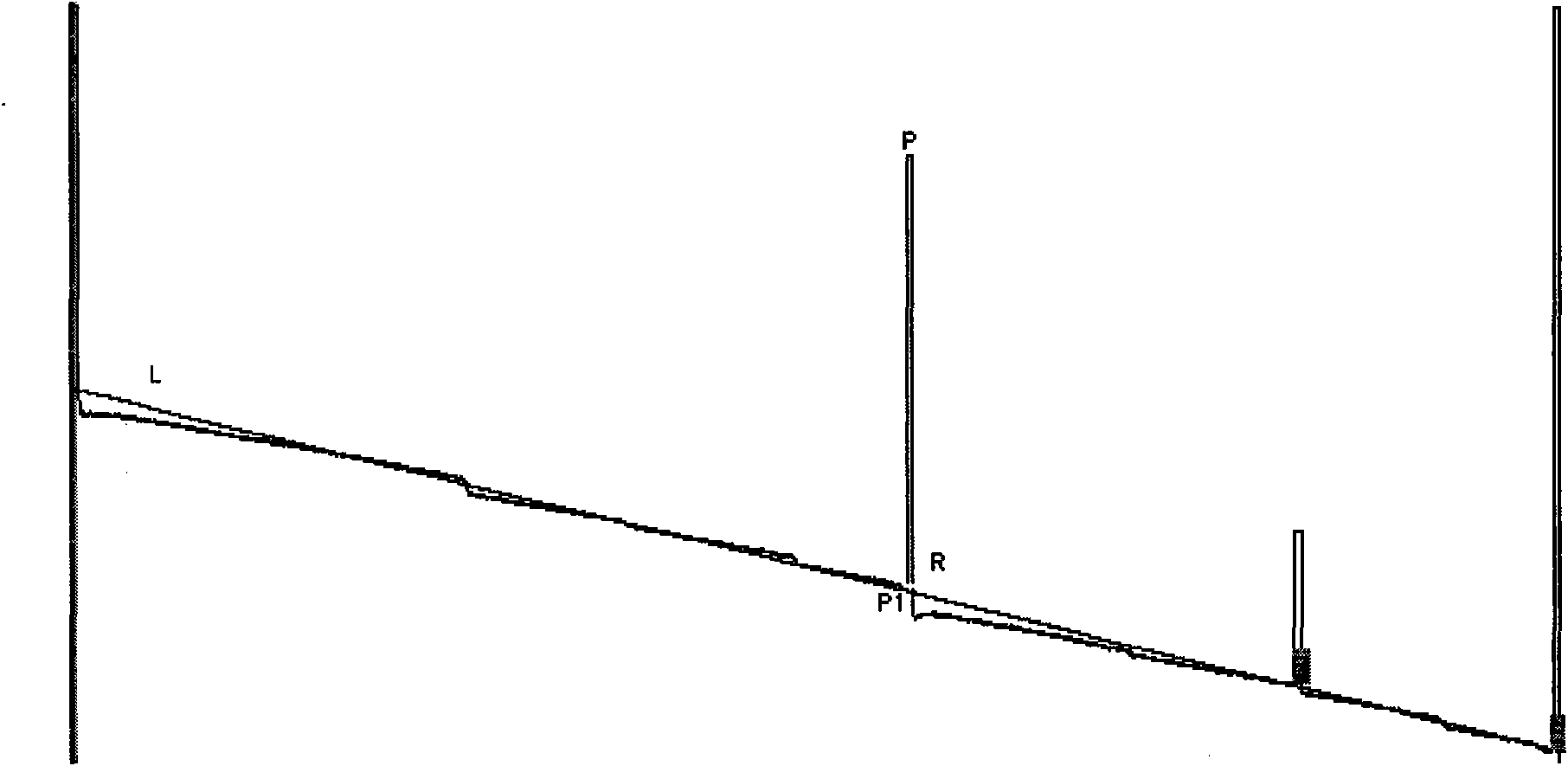
[0028] 3) From the first point of the curve to the end point E, use the least square method (LSA) to fit the straight line L, such as figure 2 .

[0029] 4) According to the ordinate difference between the test data point P and the projection P1 of the point on the straight line L, such a...


PUM


Abstract

The invention discloses a method for realizing early warning and positioning of malfunctions for a power cable network, which comprises the following steps of: starting an optical time-domain reflectometer (OTDR) by a manual or an automatic way to test an appointed fiber to acquire optical cable test data, wherein connecting lines of all sampling points form an OTDR curve of a fiber chain; forming an upward step index reflective event by reflection of light caused by an optical connector, fractures and ending points; forming a downward step index non-reflective event by bending and splicing the optical fiber which increases the attenuation of the optical fiber; finding the step index points of the curve through data analysis and determining the optical fiber event points such as optical fiber head end, tail end, optical fiber connector and splicing points and the like; determining the operation state of the optical fiber through comparison with reference data and the change of attenuation data; and sending the early warning information when the data change exceeds the early warning threshold. The invention can be used for emergency early warning and positioning when the optical fiber network degrades and is in emergent cases so that the anti-damage capacity of the communication network is strengthened and the occurrence of optical fiber blockage is reduced to a great extend.

Description

technical field [0001] This method is mainly used for the optical cable network of the power communication system, and can also be used for telecom operators such as China Telecom, China Unicom, China Netcom and China Mobile, as well as all enterprises that use optical cables as transmission lines, to provide network fault diagnosis, performance monitoring, Resource scheduling management, network management and other services. Background technique [0002] In recent years, there are various professional application systems for the monitoring and management of communication equipment in the power system. The monitoring system has been put into the line, which has played a certain role in improving the level of line operation and maintenance management, timely discovering and solving the fault problems in the line, and improving the level of safe operation of the line. However, the system construction is mainly carried out around static optical cable resource management and o...

Claims


Application Information

Patent Timeline
Patent Type & Authority Applications(China)
IPC IPC(8): H04B10/08H04B10/071
Inventor 张刚黄在朝张增华陶帮胜吴军民李炳林张浩
Owner STATE GRID ELECTRIC POWER RES INST
Learn More