
Battery system

A battery system and battery technology, applied in secondary batteries, battery temperature control, battery pack components, etc., can solve the problem of difficulty in reducing the temperature difference of battery cells, and achieve the effect of reducing temperature difference

Inactive Publication Date: 2010-11-24
SANYO ELECTRIC CO LTD
View PDF4 Cites 29 Cited by
  • Summary
  • Abstract
  • Description
  • Claims
  • Application Information

AI Technical Summary

Problems solved by technology

Therefore, there is a disadvantage that it is difficult to reduce the temperature difference of all the battery cells even when the air volume of the cooling air forcibly sent to the supply duct is changed.

Method used


Image

  • Battery system
  • Battery system
  • Battery system

Examples


Embodiment Construction

[0119] Hereinafter, embodiments of the present invention will be described based on the drawings. However, the examples shown below are examples of battery systems for embodying the technical idea of ​​the present invention, and the battery system of the present invention is not limited to the following battery systems.

[0120] In addition, in this specification, in order to facilitate understanding of claims, symbols corresponding to members shown in the embodiments are attached to members shown in “claims” and “summary of the invention”. However, the components shown in the claims must not be specified as the components of the embodiments.

[0121] Figure 2 to Figure 8 Showing a first embodiment of the invention, Figure 15 to Figure 18 Showing a second embodiment of the invention, Figure 19 to Figure 21 Showing a third embodiment of the invention, Figure 22 to Figure 24 A fourth embodiment of the present invention is shown. The battery systems shown in the above em...


PUM


Abstract

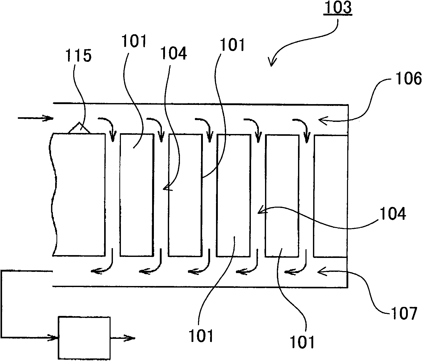
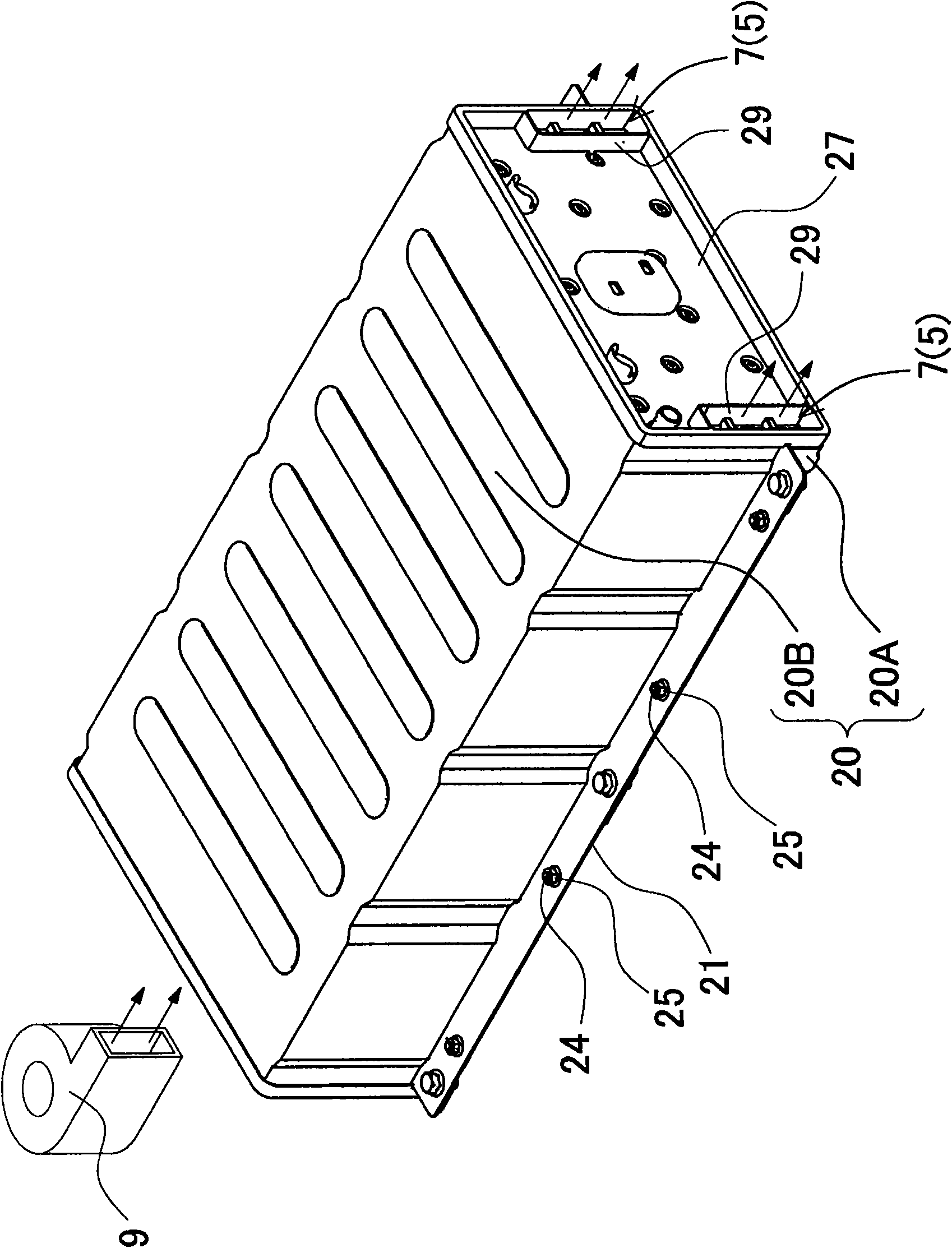
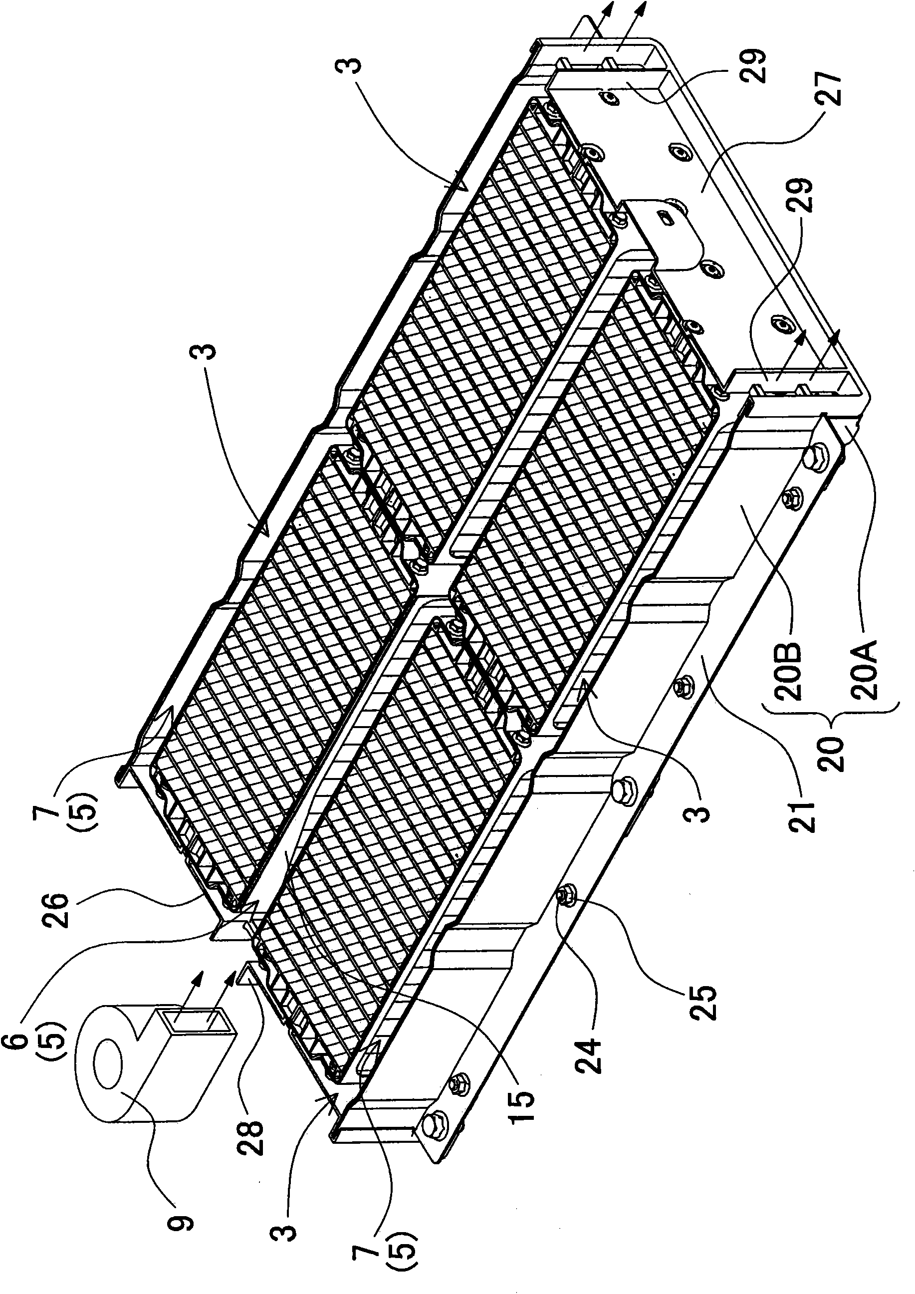
The battery system comprises battery blocks 3 having a plurality of stacked battery cells 1, ventilating ducts that are supply ducts and exhaust ducts 7 disposed on each side of the battery blocks 3, and ventilating apparatus 9. Cooling gas is forced to flow from the supply ducts through cooling gaps 4 and into the exhaust ducts 7 to cool the battery cells 1. The battery system has temperature equalizing plates 15 disposed on the supply duct sides of the battery blocks 3. These temperature equalizing plates 15 are provided with mass-flow regulating openings 16 extending in the battery cell 1 stacking direction. The area exposed by the mass-flow regulating openings 16 varies with position in the battery cell 1 stacking direction, and supply duct cooling gas passes through the mass-flow regulating openings 16 into each cooling gap 4 to equalize the temperature of all the battery cells 1.

Description

technical field [0001] The present invention relates to a battery system in which air blowing passages are provided on both sides of a battery block formed by stacking a plurality of battery cells, and the battery cells are cooled by forced air blowing from the air blowing passages to the cooling gaps of the battery blocks. Background technique [0002] A battery system in which a plurality of battery cells is stacked and forced air is blown into the cooling gap between the battery cells creates a temperature difference between the battery cells. In particular, when the number of stacked battery cells increases, it is difficult to make all the battery cells have a uniform temperature, that is, it is difficult to cool while reducing the temperature difference. In a battery system in which multiple battery cells are stacked, it is important to minimize the temperature difference between the battery cells. This is because the temperature difference of the battery cells makes t...

Claims


Application Information

Patent Timeline
Patent Type & Authority Applications(China)
IPC IPC(8): H01M10/50H01M2/10H01M10/60H01M10/613H01M10/617H01M10/625H01M10/647H01M10/6554H01M10/6557H01M10/6563
CPCH01M10/5016H01M10/5004H01M10/5032H01M10/5067H01M10/5036H01M10/5028H01M10/625H01M10/64H01M10/6563H01M10/647H01M10/651H01M10/613Y02E60/10
Inventor 藤井一广
Owner SANYO ELECTRIC CO LTD
Learn More