Eureka AIR delivers breakthrough ideas for toughest innovation challenges, trusted by R&D personnel around the world.

A Surface Wetness Sensor

A sensor and wetting technology, applied in the field of sample surface wetness measurement devices, can solve the problems of easy consumption of electrode materials, difficult sensor miniaturization, and distortion of measurement results, so as to achieve good reproducibility of measurement results, avoid material consumption, and true measurement results Effect

Active Publication Date: 2015-10-21
NO 59 RES INST OF CHINA ORDNANCE IND
View PDF3 Cites 0 Cited by
  • Summary
  • Abstract
  • Description
  • Claims
  • Application Information

AI Technical Summary

Problems solved by technology

The sensors of the above two types of ACM instruments are all made of the principle that there is a potential difference between dissimilar metals and generate galvanic corrosion currents. Their common disadvantages are (1) The electrode materials are easy to consume, resulting in the output current under the same conditions. There are large fluctuations; (2) Galvanic corrosion changes the composition of the thin liquid film, which will distort the measurement results; (3) Due to the consumption of electrode materials, it is difficult to miniaturize the sensor
[0003] So far, ACM instruments and their sensors have been limited to the measurement of wetting time

Method used


Image

  • A Surface Wetness Sensor
  • A Surface Wetness Sensor
  • A Surface Wetness Sensor

Examples


Embodiment 1

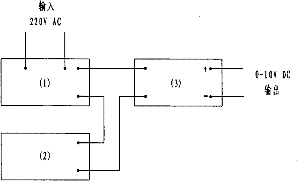
[0028] Embodiment 1: as figure 1 , image 3 As shown, a surface wetting sensor is characterized in that: it includes a signal source 1, a surface wetting sensing unit 2 and a detection output unit 3;

[0029] The signal source 1 generates an electrical signal and provides it to the surface wetting sensing unit 2; the surface wetting sensing unit 2 detects the surface wetting information and converts it into a corresponding current signal; the detection output unit 3 converts the current signal of the surface wetting sensing unit 2 into voltage signal and output.

[0030] The signal source 1 includes a reference oscillator 7, a reference voltage source 8, an electronic switch 9, a current amplifier 10 and an output interface 11;

[0031] The reference oscillator 7 generates accurate square waves, and different frequencies are selected by jumpers; the reference voltage source 8 generates a stable reference voltage, and the size of the reference voltage is changed through a var...

Embodiment 2

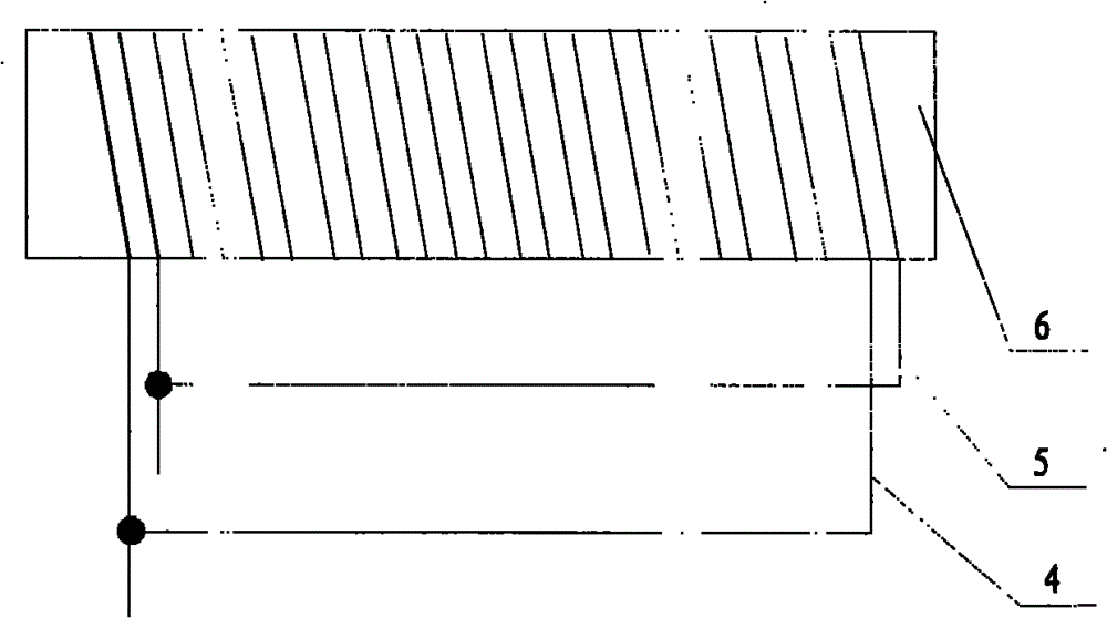
[0043] Embodiment 2: as Figure 5 As shown, the difference from Embodiment 1 is that the insulator 6 is provided with a number of micro-holes with equal spacing, and gold wires pass through the micro-holes to form parallel winding metal wires.

Embodiment 3

[0044] Embodiment 3: as Figure 6 As shown, different from Embodiments 1 and 2, the insulator 6 is only provided with microgrooves at both ends. The gold wires are wound in the grooves to form a structure parallel to each other.

[0045] The above-mentioned metal wires may be precious metal wires, or other metal wires with strong corrosion resistance.


PUM

PropertyMeasurementUnit
diameteraaaaaaaaaa

Abstract

The invention discloses a surface wettability sensor. The sensor comprises a signal source (1), a surface wettability sensing unit (2) and a detection output unit (3), wherein the signal source (1) generates an electric signal and provides the electric signal for the surface wettability sensing unit (2); the surface wettability sensing unit (2) detects surface wettability information and converts the information to a corresponding electric current signal; the detection output unit (3) converts the electric current signal of the surface wettability sensing unit (2) to a voltage signal to output; and the surface wettability sensing unit (2) comprises an insulator (6) and two metal wires (4, 5) which is wound on the insulator (6) in parallel, and the two metal wires separately form one detection electrode. The beneficial effects of the invention are as follows: sensor parameters are stable, the repeatability of the measuring result is good; the sensor is smaller and is more suitable to be used in narrow space; and electrode polarization and material consumption in liquid film can be avoided, thus the measuring result is more real.

Description

technical field [0001] The invention relates to a sample surface wetness measurement device for atmospheric corrosion test or environmental test, which is used for the measurement of the sample surface wetting time and the control of the wetness degree. Background technique [0002] The degree of surface wetting is a key factor in determining the rate of metal corrosion. This led to the development of the Atmospheric Corrosion Monitor (ACM) to measure the wetting time of sample surfaces in atmospheric environments. Since Tomashov introduced the atmospheric corrosion monitor into atmospheric corrosion research in the 1950s, it has become a relatively successful tool for researching and monitoring atmospheric corrosion through continuous research by Sereda, Kucera, Mattson, and Mansfeld. my country has used ACM for long-term monitoring of atmospheric corrosion since the 1970s. The existing ACM is divided into two types: one is the ACM of the double-electrode primary battery,...

Claims


Application Information

Patent Timeline
Patent Type & Authority Patents(China)
IPC IPC(8): G01N17/02
Inventor 杨晓然李迪凡封先河王俊芳李正雄朱玉琴
Owner NO 59 RES INST OF CHINA ORDNANCE IND
Why Eureka
Eureka Blog
Learn More