
Driven gear of engine balance shaft

A technology of driven gear and balance shaft, used in belts/chains/gears, mechanical equipment, components with teeth, etc., can solve the problem of high meshing noise, ineffective spring buffering and shock absorption, and inability to quickly attenuate impact force, etc. problem, to achieve the effect of reducing vibration and meshing noise

Inactive Publication Date: 2010-11-24
CHONGQING LONCIN MOTOR
View PDF7 Cites 7 Cited by
  • Summary
  • Abstract
  • Description
  • Claims
  • Application Information

AI Technical Summary

Problems solved by technology

This is a common buffer and shock absorbing structure on the driven gear of the engine balance shaft at present. The shock absorbing spring transmits torque between the driven gear outer cover and the shock absorbing inner cover, and can play a role in the impact force generated when the driving gear is meshed with the driven gear. The cushioning effect reduces the vibration and meshing noise to a certain extent, but due to the small damping of the spring, it cannot quickly attenuate the impact force between the driving and driven gears of the balance shaft, especially on large-displacement engines, the eccentric weight of the balance shaft The block is heavier, the inertia is greater, and the buffering and shock absorption effect of the spring is not obvious, which leads to the vibration of the engine and the meshing noise between the main and driven gears of the balance shaft are still relatively large

Method used


Image

  • Driven gear of engine balance shaft
  • Driven gear of engine balance shaft
  • Driven gear of engine balance shaft

Examples


Embodiment Construction

[0023] The present invention will be further described below in conjunction with drawings and embodiments.

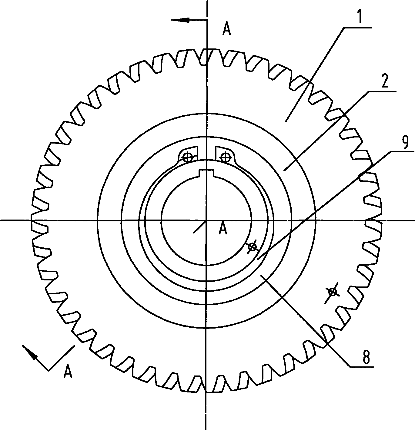
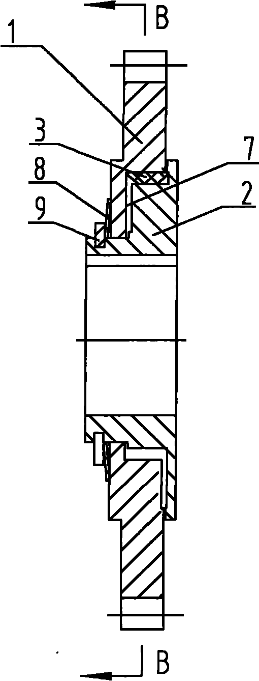
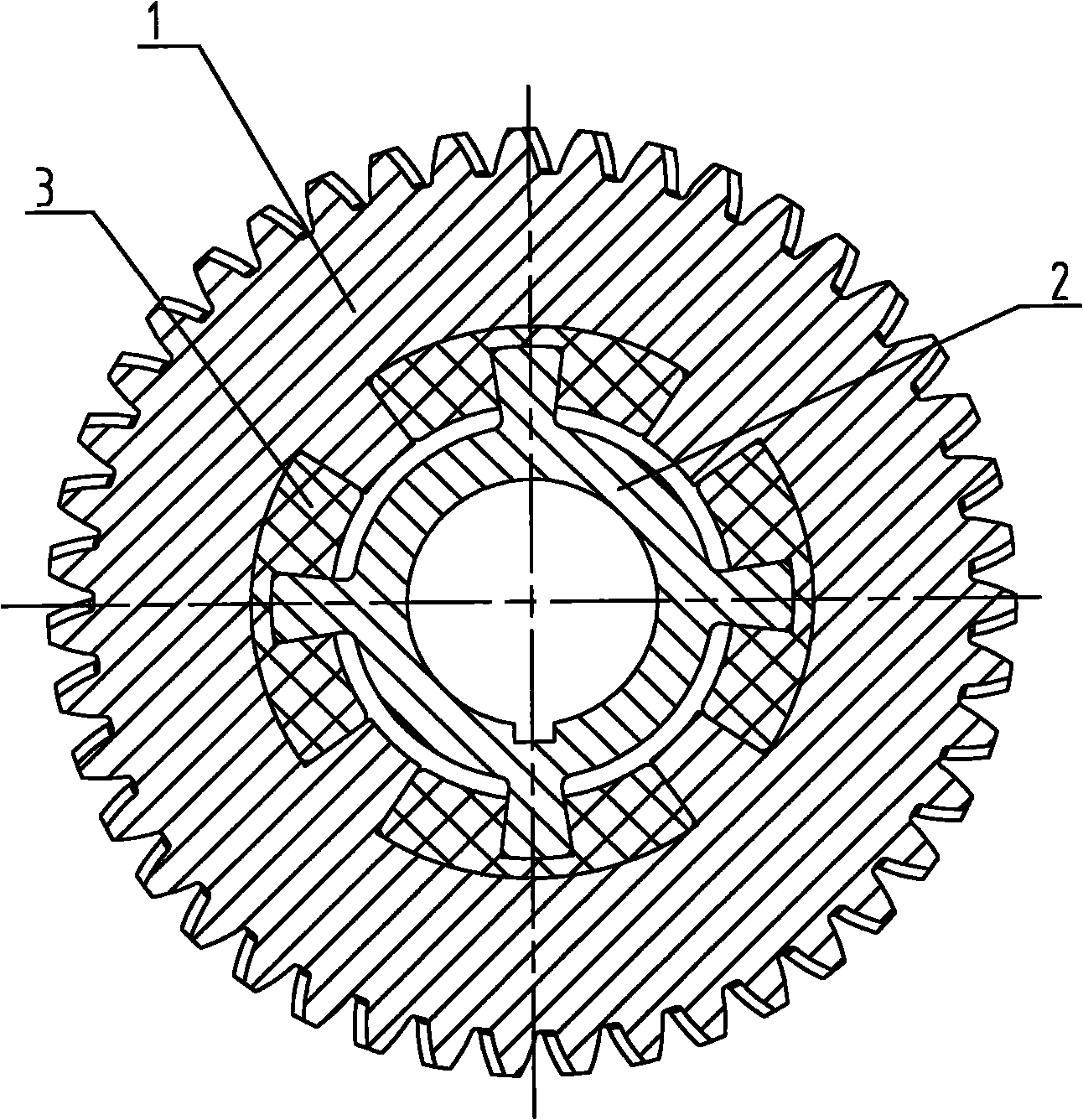
[0024] Such as figure 1 , 2 , 3, and 4, the engine balance shaft driven gear of the present invention has an outer ring gear 1 and an inner ring wheel 2, the outer ring gear 1 is assembled on the inner ring wheel 2, the outer ring gear 1 and the inner ring Between the ring wheels 2 is a gap fitting structure similar to splines, and a rubber block 3 is arranged between the adjacent key teeth of the outer ring gear 1 and the inner ring wheel 2 .

[0025] In the present invention, the shock absorbing structure of the outer ring gear 1 and the inner ring wheel 2 in the direction of rotation is designed as a full rubber shock absorber. The rubber has relatively large damping and can quickly attenuate impact, thereby achieving a good shock absorbing effect. At the same time, the rubber block 3 prevents mechanical contact between the outer ring gear 1 and the inner ring whee...


PUM


Abstract

The invention provides a driven gear of an engine balance shaft, comprising an outer ring gear (1) and an inner ring wheel disc (2). The outer ring gear (1) is assembled on the inner ring wheel disc (2), a spline-like gap assembly structure is arranged between the outer ring gear (1) and the inner ring wheel disc (2), a rubber block (3) is arranged between adjacent spline teeth of the outer ring gear (1) and the inner ring wheel disc (2), and teeth engaged with a drive gear of a balance shaft arranged on the outer ring gear (1) are skewed teeth. By using the technical scheme, the invention can effectively reduce the vibration of an engine and decrease engagement noise between the drive gear and the driven gear of the balance shaft.

Description

technical field [0001] The invention relates to a gear, especially a gear on a balance shaft of an engine. Background technique [0002] The balance shaft is an eccentrically weighted shaft in the engine that fits near the crankshaft. When the engine is working, the balance shaft rotates synchronously with the crankshaft, and the reverse vibration force generated by the eccentric weight is used to achieve a good balance of the engine and reduce the vibration of the engine. Power transmission is realized between the crankshaft and the balance shaft through the balance shaft driving and driven gears, the balance shaft driving gear is fixedly connected to the crankshaft, and the balance shaft driven gear is fixedly connected to the balance shaft. [0003] When the speed of the balance shaft driving gear fluctuates, an impact load will appear between the balance shaft driven gear and the balance shaft driving gear under the action of the balance shaft eccentric counterweight in...

Claims


Application Information

Patent Timeline
Patent Type & Authority Applications(China)
IPC IPC(8): F16H55/17
Inventor 何建祥韩秋
Owner CHONGQING LONCIN MOTOR
Learn More