
Anode used for aluminum electrolysis

An aluminum electrolysis and anode technology, which is applied in the field of new structure anodes, can solve the problems of increased energy consumption of electrolytic aluminum and difficulty in discharging carbon dioxide gas, and achieves the effects of reducing electrolysis energy consumption, reducing the bottom coverage area, and reducing voltage

Inactive Publication Date: 2010-11-24
重庆天泰铝业股份有限公司
View PDF1 Cites 6 Cited by
  • Summary
  • Abstract
  • Description
  • Claims
  • Application Information

AI Technical Summary

Problems solved by technology

[0004] The purpose of the present invention is to solve the above-mentioned deficiencies in the prior art, to solve the problem that the carbon dioxide gas generated in the process of electrolytic aluminum is difficult to discharge, so that the energy consumption of electrolytic aluminum is increased, and to provide a method that can quickly discharge the gas at the bottom of the anode, Anodes for Aluminum Electrolysis Effectively Reduce Energy Consumption

Method used


Image

  • Anode used for aluminum electrolysis
  • Anode used for aluminum electrolysis
  • Anode used for aluminum electrolysis

Examples


Embodiment 1

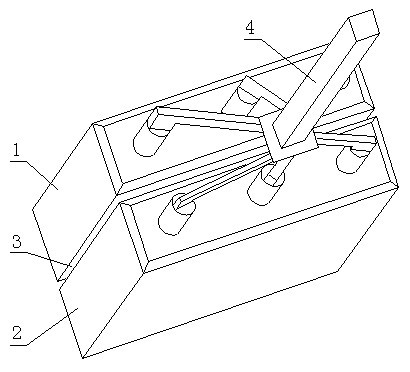
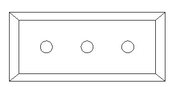
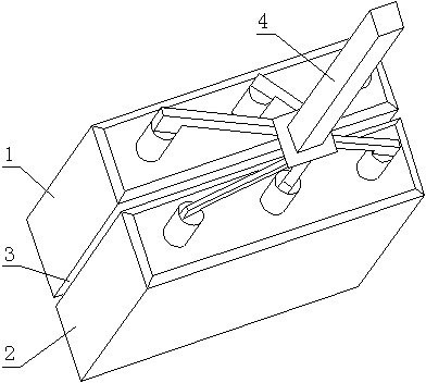
[0016] Embodiment 1: as figure 1 and figure 2 As shown, an anode for aluminum electrolysis includes a first carbon block 1 and a second carbon block 2, the first carbon block 1 and the second carbon block 2 are placed in parallel, and the first carbon block 1 and the second A channel 3 for exhaust is reserved between the carbon blocks 2, and the first carbon block 1 and the second carbon block 2 are all connected to the power supply through steel claws 4; the widths of the first carbon block 1 and the second carbon block 2 are both The width of the channel 3 between the first carbon block 1 and the second carbon block 2 is 20 mm.

Embodiment 2

[0017] Embodiment 2: another anode for aluminum electrolysis is based on embodiment 1, the width of the first carbon block 1 and the second carbon block 2 are all set to 430 mm, the first carbon block 1 and the The width of the channel 3 between the second carbon blocks 2 is set to 40 mm. Here, the width of the first carbon block 1 and the second carbon block 2 and the width of the channel 3 are all adopted with a larger value, because the amount of air bubbles produced by using a wider carbon block is larger, so the corresponding larger value is adopted. The wide channel 3 can increase the discharge flow rate of air bubbles, so as to achieve the purpose of accelerating exhaust.

Embodiment 3

[0018] Embodiment 3: another anode for aluminum electrolysis is based on embodiment 1, the width of the first carbon block 1 and the second carbon block 2 are all set to 360 mm, the first carbon block 1 and the The width of the channel 3 between the second carbon blocks 2 is set to 10 mm. In this embodiment, the configuration with a smaller size is adopted, because after reducing the width of the first carbon block and the second carbon block, the flow distance of the gas at the bottom of the anode is shortened, and it can be quickly discharged from both sides of the carbon block. Therefore, the width of the middle channel 3 can be correspondingly reduced.

[0019] Here, simulation calculations were carried out for the anode according to the invention using a carbon block with a width of 400 mm. In this case, the thickness of the bubble layer at the bottom of the anode is 1.389~1.414 cm, and 1.4 cm is taken as the average value here. Therefore, when the thickness of the bubbl...


PUM

PropertyMeasurementUnit
widthaaaaaaaaaa

Abstract

The invention relates to an anode used for aluminum electrolysis. The anode comprises a first carbon block and a second carbon block, wherein the first carbon block and the second carbon block are arranged in parallel; a channel for exhausting air is reserved between the first carbon block and the second carbon block; both the first carbon block and the second carbon block are connected with a power supply by steel talons; and the width range of the first carbon block and the second carbon block is between 360 and 430 mm. The anode used for the aluminum electrolysis of the invention can quicken the exhausting speed of the air at the bottom of an anode block, greatly reduce the coverage area of the bottom of the anode block and efficiently prevent air bubbles from forming an air bubble layer, so that the aims of reducing a resistance value in an electrolytic tank and reducing the electrolytic energy consumption are fulfilled.

Description

technical field [0001] The invention relates to the improvement technology of the anode structure used in the production of electrolytic aluminum, in particular to a novel structural anode for aluminum electrolysis. Background technique [0002] In the industrial production of aluminum electrolysis, metal aluminum is mainly produced by cryolite-alumina molten salt electrolysis. Its production equipment includes an electrolytic cell lined with carbonaceous materials. Between the steel shell of the electrolytic cell and the carbonaceous lining are refractory materials and insulation bricks. The carbonaceous lining of the electrolytic cell is generally made of Carbon bricks made of corrosive anthracite or graphite materials or a mixture of the two are built, and the joints between them are tamped with carbon paste made of carbon materials. A cathode steel rod is placed at the bottom of the electrolytic cell and extends out of the shell of the electrolytic cell. A carbon anode ...

Claims


Application Information

Patent Timeline
Patent Type & Authority Applications(China)
IPC IPC(8): C25C3/12
Inventor 田应甫李贺松
Owner 重庆天泰铝业股份有限公司
Learn More