
Distribution device of electronic component

A technology for electronic components and distribution devices, applied in the directions of measuring devices, sorting, measuring electricity, etc., can solve the problems of increased compressed air resistance, increased compressed air flow, stagnant compressed air flow, etc.

Active Publication Date: 2010-11-24
SHIBUYA IND CO LTD
View PDF7 Cites 10 Cited by
  • Summary
  • Abstract
  • Description
  • Claims
  • Application Information

AI Technical Summary

Problems solved by technology

[0006] For this reason, the cross-sectional area of ​​the flow path rapidly expands at the connection between the injection pipe and the swing pipe. At this connection, the compressed air in the injection pipe expands. Air leakage occurs in the gap, so that the flow velocity of the compressed air decreases at the above-mentioned connection part, and there is a problem that the flow of the compressed air stagnates
[0007] In addition, when the distribution destination of the electronic components by the swing tube is the end away from the central part of the distribution member, the swing angle of the swing tube becomes larger than that of the input tube, so the compressed air is received from the inner wall surface of the swing tube. The resistance becomes larger, which in turn increases the flow rate of compressed air
There is little lost time for each electronic component to be processed, but the larger the number of electronic parts to be processed, the more the lost time accumulates, and it becomes a large loss of the time required for allocating processing

Method used


Image

  • Distribution device of electronic component
  • Distribution device of electronic component
  • Distribution device of electronic component

Examples


Embodiment Construction

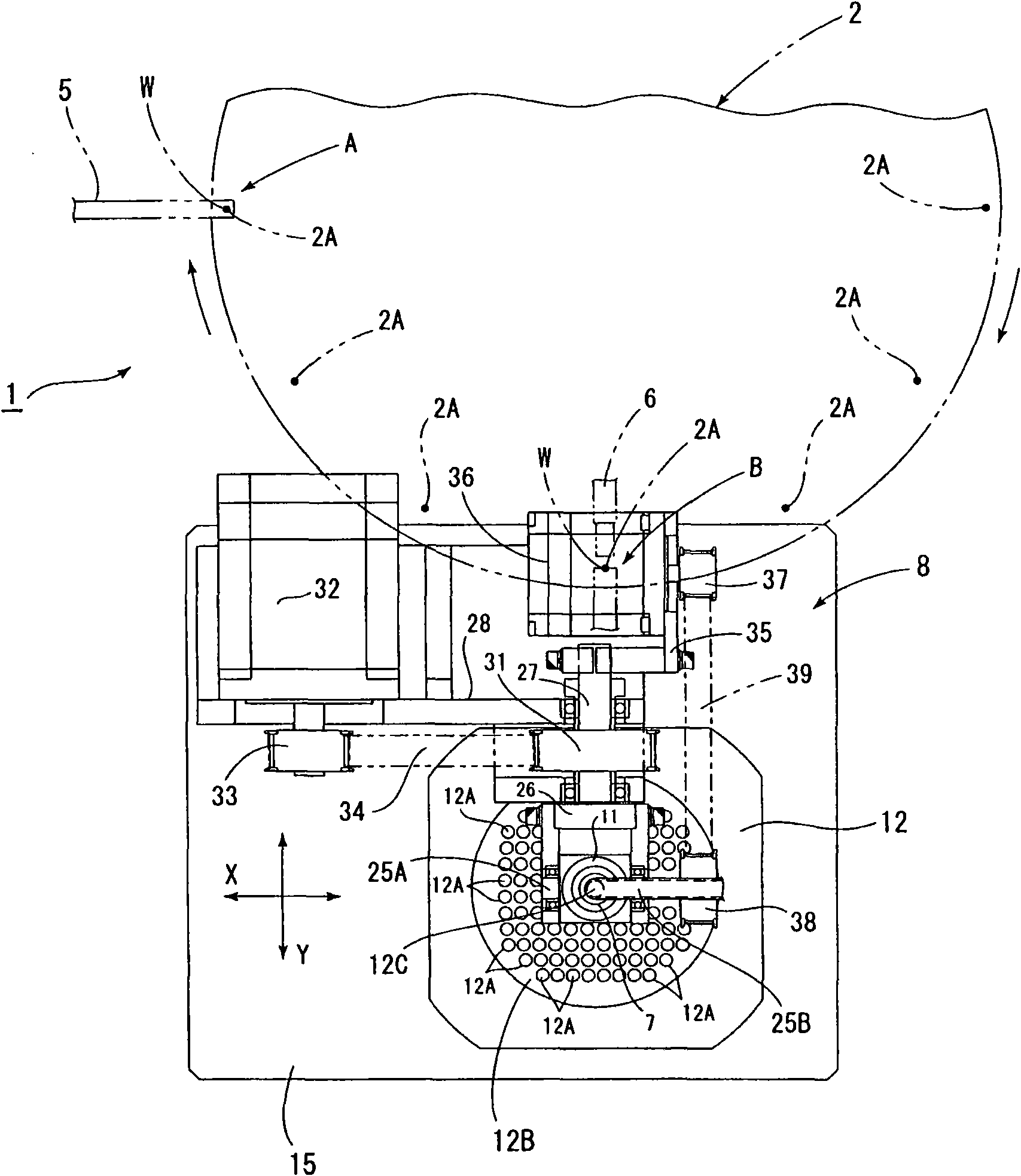
[0014] Hereinafter, embodiments of the present invention will be described based on the drawings. in Figure 1 ~ Figure 2 In the figure, the symbol 1 is a classification device that classifies a plurality of electronic components W (chip-type LEDs) into each quality class of electrical characteristics.

[0015] The sorting device 1 has a turntable 2, a quality inspection device not shown in the figure, a distribution device 3, and a control device 4; the turntable 2 sucks and holds the electronic components W intermittently transported in the arrow direction; the quality inspection device The quality of each electronic component W transported by the turntable 2 is inspected; the distribution device 3 is arranged at a position adjacent to the turntable 2, and distributes the electronic components W whose quality has been inspected by the above-mentioned quality inspection device according to the quality level; the control device 4 controls The operation of the turntable 2, the qu...


PUM


Abstract

The invention provides a distribution device of an electronic component; an inputting slideway (7) of the distribution device (3) comprises flexible tubes; the lower end of the inputting slideway (7) is held at the lower end of a swinging component (11). The swinging component (11) is driven by a driving mechanism (8) to swing so that an exhausting port (7B) of the inputting slideway (7) moves to a position adjacent to the upper part of a specific distribution port (12A). The flow area in the inputting slideway (7) is in the whole area, which can prevent the flowing speed of the compressed air flowing into the inputting slideway (7) from reducing. Therefore, the distribution device (3) of the electronic component with a higher processing is provided.

Description

Technical field [0001] The present invention relates to an electronic component dispensing device, and more specifically, to an electronic component dispensing device that dispenses electronic components corresponding to different quality levels. Background technique [0002] Conventionally, there has been proposed a classification device for classifying electronic components according to the difference in quality level, and assigning electronic components to each level (for example, Patent Document 1). [0003] In the above-mentioned conventional sorting device, there is an input pipe and a swing pipe; the input pipe is arranged vertically downward to form a discharge port at the lower end; the swing pipe is inserted into the lower end of the input pipe, and the drive mechanism The position of the lower end is the swing fulcrum for swinging; the position of the swing fulcrum of the swing pipe is connected to the vicinity of the lower end of the input pipe through a spherical seali...

Claims


Application Information

Patent Timeline
IPC IPC(8): B07C5/36
CPCG01R29/00G01R31/01
Inventor 堀俊一
Owner SHIBUYA IND CO LTD
Learn More