Metallic heat exchanger tube

An exchanger tube, metal heat technology, applied in heat exchange equipment, indirect heat exchangers, metal processing equipment, etc., can solve problems such as unfavorable blocking of heat transfer, and achieve the effect of reducing dangerous potential and reducing production costs.

Active Publication Date: 2010-11-17
WIELAND WERKE AG
View PDF12 Cites 8 Cited by
  • Summary
  • Abstract
  • Description
  • Claims
  • Application Information

AI Technical Summary

Problems solved by technology

Thus forming an undesirable liquid film which adversely prevents heat transfer

Method used


Image

  • Metallic heat exchanger tube
  • Metallic heat exchanger tube
  • Metallic heat exchanger tube

Examples


Embodiment Construction

[0036] Mutually corresponding parts are represented by the same example in all figures.

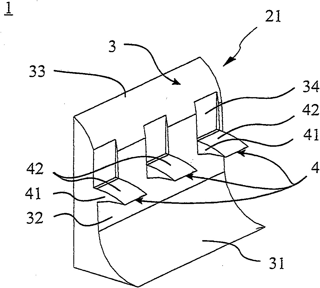
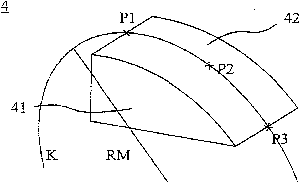
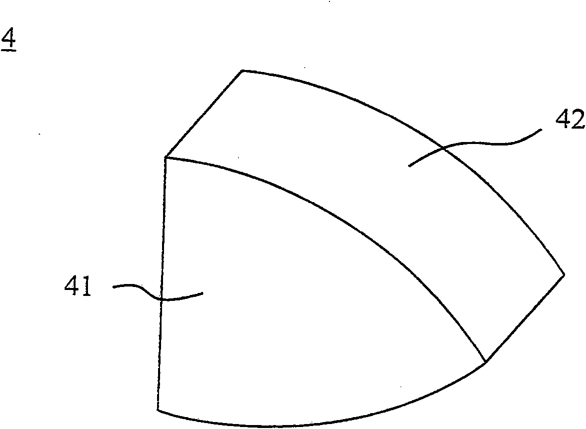
[0037] figure 1 A perspective sectional view showing a rib section of a heat exchanger tube with three material projections 4 . The surrounding, integrally formed rib 3 is only partially formed from the tube outer side 21 . The rib 3 has a rib foot 31 , which is placed against the tube wall shown in the illustration here, a rib side wall 32 and a rib tip 33 . The ribs 3 are at a substantially radial distance from the pipe wall. The rib side wall 32 is equipped with an additional structural element, which is formed by a material projection 4 , which is placed laterally on the rib side wall 32 . The material projections 4 have delimiting surfaces 41 and 42 . In the embodiment formed, the three illustrated limiting surfaces 42 of the material projection 4 are curved convexly on the side facing the tube wall. In principle, however, according to the invention each material projection part...


PUM


Abstract

The invention relates to a metallic heat exchanger tube (1) with a tube wall (2) and with integrally formed ribs (3) which run around on the tube outside (21) and which have a rib foot (31), rib flanks (32) and a rib tip (33), the rib foot (31) projecting essentially radially from the tube wall (2), and the rib flanks (32) being provided with additional structural elements which are formed as material projections (4) arranged laterally on the rib flank (32), the material projections (4) having a plurality of boundary faces (41, 42), at least one of the boundary faces (42) of at least one material projection (4) being curved convexly.

Description

technical field [0001] The invention relates to a metallic heat exchanger tube according to the preamble of claim 1 . Background technique [0002] Such metal heat exchanger tubes are used in particular for the condensation of liquids consisting of pure substances or mixtures on the outside of the tubes. Condensation occurs in many fields in cooling and climate technology as well as in process and energy technology. Tube-bundle heat exchangers are frequently used in which vapors of pure substances or mixtures are liquefied on the outside of the tubes and heated to brine or water on the inside of the tubes. Such an apparatus is called a tube bundle condenser or a tube bundle liquefier. [0003] Heat exchanger tubes for tube bundle heat exchangers generally have at least one structured region as well as smooth end ends and possibly smooth intermediate ends. Smooth end or center tips limit the structured area. The tubes can thus be installed without problems in the tube bun...

Claims


Application Information

Patent Timeline
Patent Type & Authority Applications(China)
IPC IPC(8): F28F1/12F28F1/42
CPCF28F1/36F28F2215/10F28F1/26F28F1/40F28F1/422F28D2021/0061B21J5/068F28F1/10F28F1/12F28F1/24F28F1/32F28F1/42F28F13/18
Inventor 安德烈·博伊特勒阿基姆·戈特巴姆让·埃尔·哈杰勒罗纳德·卢茨
Owner WIELAND WERKE AG
Why Eureka
Try Eureka