Method for fixing gangue dumping platform in process of using permanent derrick to construct well

A fixing method and derrick technology, applied to drilling equipment, earthwork drilling, supporting devices, etc., can solve the problems of high technical requirements, small usable area of ​​the platform, large amount of recovery, etc., and achieve the effect of expanding the usable area

Inactive Publication Date: 2010-11-10
CHINA COAL NO 5 CONSTR
View PDF5 Cites 0 Cited by
  • Summary
  • Abstract
  • Description
  • Claims
  • Application Information

AI Technical Summary

Problems solved by technology

The former has complex construction procedures, small usable platform area, high technical requirements, and many potential safety hazards. It is often necessary to change the original design, prolong the preparation time for wellbore construction, and require a large amount of maintenance and restoration during use, occupying wellhead space, and reducing Utilization rate will inevitably affect the efficiency of mechanized facilities for wellbore operations; the latter will increase the installation and removal of temporary derricks, prolong the preparation time for wellbore construction and permanent installation preparation time, and take up a long construction period

Method used


Image

  • Method for fixing gangue dumping platform in process of using permanent derrick to construct well
  • Method for fixing gangue dumping platform in process of using permanent derrick to construct well
  • Method for fixing gangue dumping platform in process of using permanent derrick to construct well

Examples


Embodiment Construction

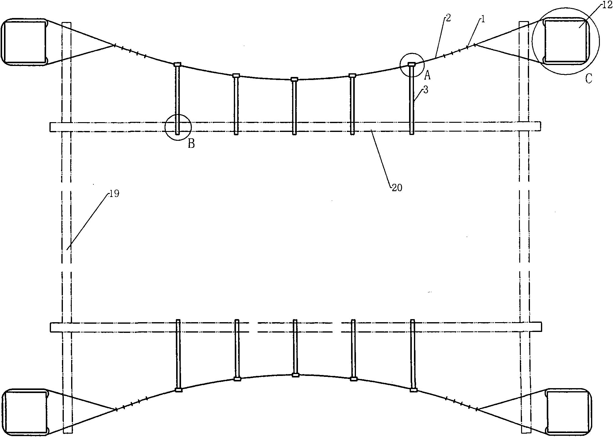
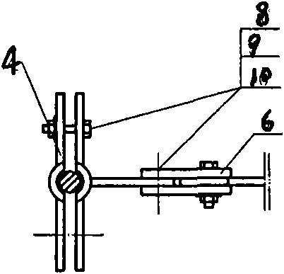
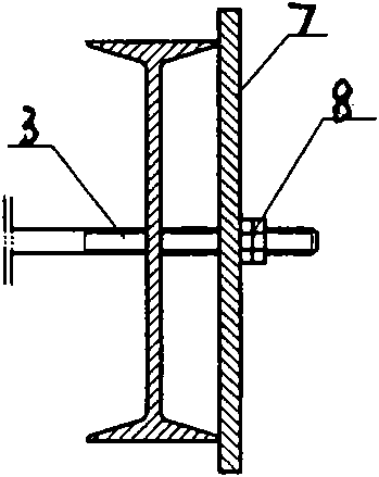
[0014] like Figure 1-Figure 6 As shown, the gangue turning platform is set at the appropriate height of the permanent derrick. The height of the turning gangue platform is determined according to the needs of the site. The corbels 18 are respectively fixed with bolts on each derrick leg 12 of the permanent derrick. The bolt specifications, quantity and design of the corbels are calculated according to depends. Two steel beams are installed on the corbel, that is, steel beam A19. The steel beam section is selected as the objective function. The force of the steel beam is mainly to bear the horizontal load, and the vertical load only considers the initial plane load of the platform before the suspender is set up. Taking the center line of the wellbore as the benchmark, two steel beams, namely steel beam B20, are symmetrically arranged on the steel beam A19. The above structure forms a platform frame, and then a certain number of small beams are supplemented according to the wel...


PUM


Abstract

The invention discloses a method for fixing a gangue dumping platform in a process of using a permanent derrick to construct a well, belonging to derrick construction. The method comprises reinforcement in horizontal direction and reinforcement in vertical direction, wherein the reinforcement in horizontal direction comprises the following steps: installing a rope protective device on derrick legs, welding the rope protective device with a pulling plate into a whole to embrace the derrick legs; connecting a steel wire rope between the derrick legs, leading the steel wire rope to pass through the rope protective device and then clamping the steel wire rope by a steel wire rope clip; and connecting a board clip I at one end of the pulling plate with the steel wire rope and connecting the other end of the board clip I with a steel beam B. The reinforcement in vertical direction comprises the following steps: installing a suspension-dragging steel wire rope on the derrick legs above the gangue dumping platform, leading the steel wire rope to pass through the and then clamping the steel wire rope by a steel wire rope clip; and installing lifting lugs on a steel beam A, installing a rope protective ring on a pulling plate clamp, leading one end of the steel wire rope to pass through the rope protective ring to be connected with a pulling plate clamp and leading the other end of the steel wire rope to be connected with a turn-buckle through the rope protective ring and connecting the other end of the turn-buckle with the lifting lug. The method has the effects of reasonably solving the relation between the platform and the derrick and the relation between the platform and a well mouth, and expanding the usable area of the well mouth to the greatest extent.

Description

technical field [0001] The invention relates to a gangue turning platform, in particular to a method for fixing the gangue turning platform when a permanent derrick is used to build a well. Background technique [0002] In order to shorten the construction period and reduce the permanent modification time, the permanent derrick is often used as a temporary sinking derrick at present. There are currently two ways to set up the gangue platform: one is the method of using the inner casing, and the other is the method of setting the temporary derrick. The former has complex construction procedures, small usable platform area, high technical requirements, and many potential safety hazards. It is often necessary to change the original design, prolong the preparation time for wellbore construction, and require a large amount of maintenance and restoration during use, occupying wellhead space, and reducing The utilization rate will inevitably affect the efficiency of mechanized fac...

Claims


Application Information

Patent Timeline
Patent Type & Authority Applications(China)
IPC IPC(8): E21B15/00
Inventor 张小美吕红娟王鹏越吴悦光
Owner CHINA COAL NO 5 CONSTR
Why Eureka
Try Eureka