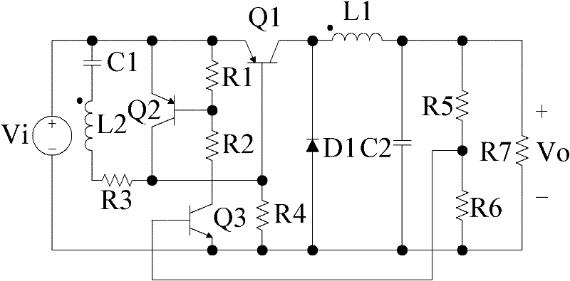
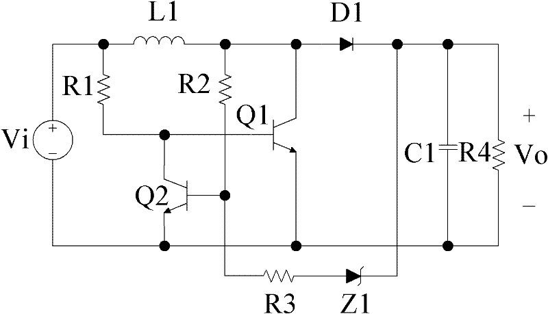
Bipolar transistor self-exciting Buck-Boost converter
A technology of bipolar transistors and converters, which is applied in the direction of converting DC power input to DC power output, instruments, and adjusting electric variables, etc., and can solve the problem of narrow application range and complex circuit structure of self-excited step-up DC-DC converters Problems such as the number of components, etc., to achieve the effect of fewer components and simple circuit structure
- Summary
- Abstract
- Description
- Claims
- Application Information
AI Technical Summary
Problems solved by technology
Method used
Image
Examples
Embodiment 1
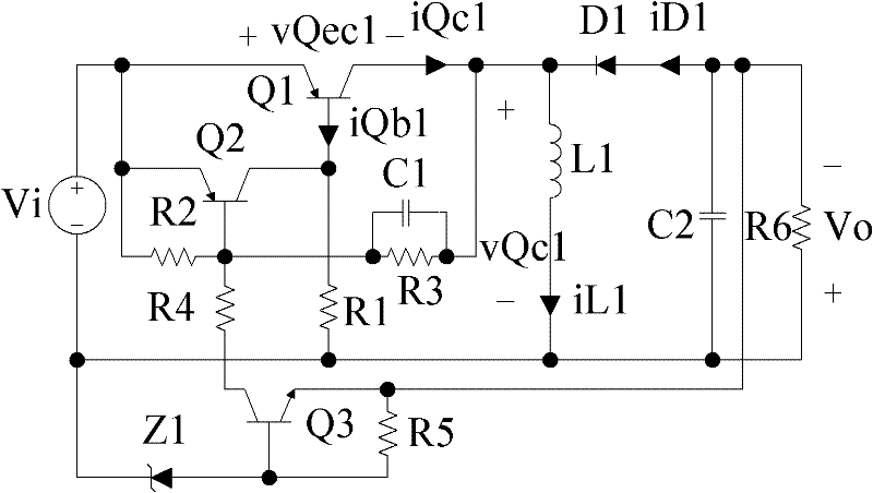
[0022] refer to image 3 and Figure 5, a bipolar transistor type self-excited Buck-Boost converter, including the main circuit of the Buck-Boost converter composed of PNP transistor Q1, inductor L1, diode D1 and capacitor C2, the voltage across the load R6 is the DC output voltage Vo, the negative terminal of the DC input voltage Vi is connected to the positive terminal of the DC output voltage Vo, the load R6 is connected in parallel with the capacitor C2, and the contact point between the negative terminal of the DC output voltage Vo and the capacitor C2 is connected to the anode of the diode D1, so The cathode of the diode D1 is connected to one end of the inductance L1, the other end of the inductance L1 is connected to the negative end of the DC input voltage Vi, the positive end of the DC output voltage Vo and the contact point of the capacitor C2 are connected to the negative end of the DC input voltage Vi connected, the self-excited Buck-Boost converter also includes...
Embodiment 2
[0028] refer to Figure 4 and Figure 6 , the present embodiment also includes a current feedback branch: one end of the parallel branch of the detection resistor R5 and the capacitor C3 is connected with the resistor R6 and the base of the NPN transistor Q3, and the other end is connected with the capacitor C2 and the emitter of the NPN transistor Q3; Q3 The collector of Q3 is connected to the base of Q2 through resistor R4, and the emitter of Q3 is connected to the anode of diode D1.
[0029] The working process of this embodiment is:
[0030] (1) The power-on start-up stage of the circuit is the same as that of Embodiment 1. After several cycles, when the output current of the circuit reaches the set value Io, the circuit has just completed the power-on start-up process and enters the steady-state working stage.
[0031] (2) The steady-state working stage of the circuit: when the output current of the circuit reaches the set value Io, the current feedback branch of the ci...
PUM
 Abstract
Description
Claims
Application Information
 - R&D
- Intellectual Property
- Life Sciences
- Materials
- Tech Scout
- Unparalleled Data Quality
- Higher Quality Content
- 60% Fewer Hallucinations
Browse by: Latest US Patents, China's latest patents, Technical Efficacy Thesaurus, Application Domain, Technology Topic, Popular Technical Reports.
© 2025 PatSnap. All rights reserved.Legal|Privacy policy|Modern Slavery Act Transparency Statement|Sitemap|About US| Contact US: help@patsnap.com


