Bipolar transistor self-exciting Zeta converter

A bipolar transistor, transistor technology, applied in the direction of converting DC power input to DC power output, instruments, adjusting electrical variables, etc., can solve the problem of narrow application range and complex circuit structure of self-excited boost DC-DC converter. The problem of the number of components, etc., can make up for the single voltage conversion function, the small number of components, and the simple circuit structure.

Active Publication Date: 2010-11-03
苏州卫优知识产权运营有限公司
View PDF8 Cites 7 Cited by
  • Summary
  • Abstract
  • Description
  • Claims
  • Application Information

AI Technical Summary

Problems solved by technology

[0005] In order to overcome the disadvantages of the existing self-excited step-down DC-DC converter with complex circuit structure, large number of components, and the narrow application range of the self-excited step-up DC-DC converter, the present invention provides a circuit structure Bipolar transistor type self-excited Zeta converter that is simple, has a small number of components, and broadens the application range

Method used


Image

  • Bipolar transistor self-exciting Zeta converter
  • Bipolar transistor self-exciting Zeta converter
  • Bipolar transistor self-exciting Zeta converter

Examples


Embodiment 1

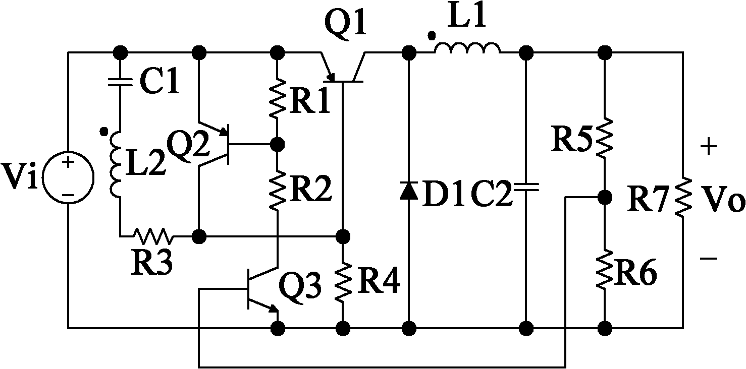
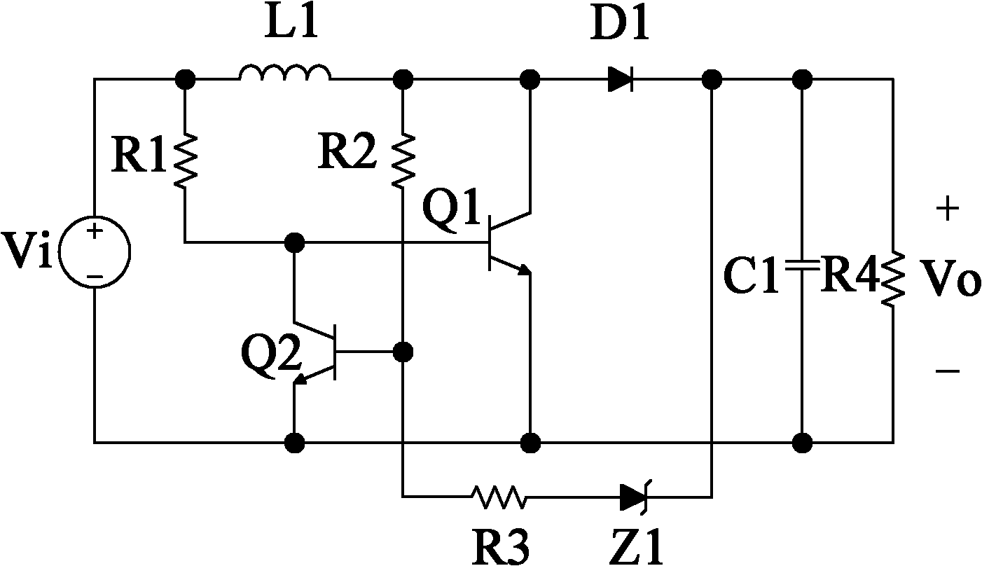
[0023] refer to image 3 and Figure 5 , a bipolar transistor-type self-excited Zeta converter, including PNP transistor Q1, inductor L1, capacitor C2, diode D1, inductor L2 and capacitor C3 to form the main circuit of the Zeta converter, and the voltage at both ends of the load R6 is a DC output Voltage Vo, the negative terminal of the DC input voltage Vi is connected to the negative terminal of the DC output voltage Vo, the load R6 is connected in parallel with the capacitor C3, the positive terminal of the DC output voltage Vo and the contact point of the capacitor C3 are connected to one end of the inductor L2, The other end of the inductor L2 is respectively connected to one end of the capacitor C2 and the cathode of the diode D1, the anode of the diode D1 is connected to the negative end of the DC input voltage Vi, the other end of the capacitor C2 is connected to one end of the inductor L1, The other end of the inductor L1 is connected to the negative terminal of the D...

Embodiment 2

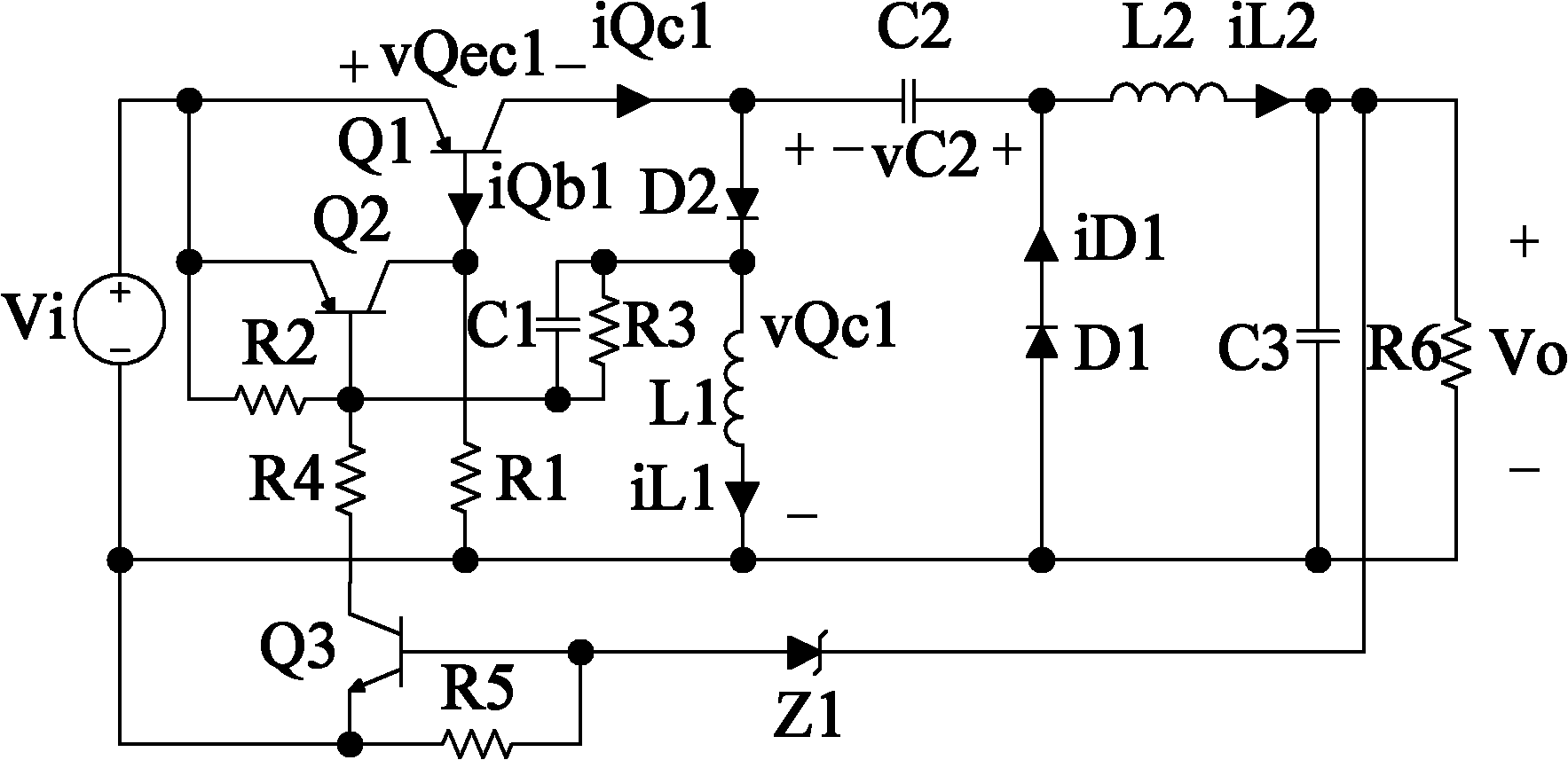
[0030] refer to Figure 4 and Figure 6 , the present embodiment also includes a current feedback branch: one end of the parallel branch of the detection resistor R5 and the capacitor C4 is connected with R6 and the base of the NPN transistor Q3, and the other end is connected with the negative terminal of Vi; the collector of Q3 is connected through the resistor R4 It is connected to the base of Q2, and the emitter of Q3 is connected to the negative terminal of Vi.

[0031] The working process of this embodiment is:

[0032] (1) The power-on start-up stage of the circuit is the same as that of Embodiment 1. After several cycles, when the output current of the circuit reaches the set value Io, the circuit has just completed the power-on start-up process and enters the steady-state working stage.

[0033] (2) The steady-state working stage of the circuit: when the output current of the circuit reaches the set value Io, the current feedback branch of the circuit starts to work...


PUM


Abstract

A bipolar transistor self-exciting Zeta converter comprises a PNP transistor Q1, an inductor L1, a capacitor C2, a diode D1, an inductor L2 and a capacitor C3 which form a main circuit of the Zeta converter and also comprises a PNP transistor Q2, wherein the emitting electrode of the PNP transistor Q1 is connected with the positive terminal of direct current input voltage Vi; the junction of the inductor L1 and the capacitor C2 is connected with the collecting electrode of the PNP transistor Q1; the emitting electrode and the collecting electrode of the PNP transistor Q2 are respectively connected with the emitting electrode and the base electrode of the PNP transistor Q1; the base electrode of the PNP transistor Q1 is also connected to the negative terminal of direct current input voltage Vi by a resistor R1; series branch circuits of a resistor R2 and a resistor R3 are connected at the two ends of the emitting electrode and the collecting electrode of the Q1 in parallel; and the junction of the resistor R2 and the resistor R3 is connected with the base electrode of the PNP transistor Q2. The converter has simple circuit structure, a few of components and widened application range.

Description

technical field [0001] The invention relates to a self-excited direct current-direct current converter, which is applied to a low-power switch voltage stabilized / current-stabilized power supply, a high-brightness LED drive circuit, etc., in particular to a self-excited Zeta converter. Background technique [0002] Compared with low-power linear power supply and low-power self-excited DC-DC converter, low-power self-excited DC-DC converter has simple circuit structure, fewer components, low cost, good self-starting and self-protection performance, It has the advantages of wide working voltage range and high efficiency. [0003] Chinese patent ZL99108088.2 discloses a self-excited step-down DC-DC converter, such as figure 1 shown. The main loop of the Buck converter is composed of PNP transistor Q1, coupling inductor L1, diode D1 and capacitor C2. Vi and Vo are the DC input and output voltages respectively, and R7 is the load. The coupled inductor L2 is connected to the emi...

Claims


Application Information

Patent Timeline
IPC IPC(8): H02M3/158
Inventor 陈怡
Owner 苏州卫优知识产权运营有限公司
Why Eureka
Try Eureka