
Flow control device

A flow control device and controller technology, applied in the direction of mass flow measurement device, flow control using electrical devices, etc., can solve the problems of inaccurate metering of metering pumps, low metering accuracy of flow control devices, and lax closing, etc. Measurement accuracy, stable flow, and the effect of solving backflow

Inactive Publication Date: 2010-10-27
奥斯汀新材料(张家港)有限公司
View PDF5 Cites 5 Cited by
  • Summary
  • Abstract
  • Description
  • Claims
  • Application Information

AI Technical Summary

Problems solved by technology

[0004] The disadvantage of the existing flow control device is: since the pressure in the metering tank will change correspondingly when the material is fed or discharged, when the pressure in the metering tank is relatively high, the flow rate of the material will decrease at the same speed and time of the metering pump. It must be relatively large. When the pressure in the metering tank is small, the flow rate of the material must be small at the same speed and time of the metering pump, resulting in inaccurate metering of the metering pump; Strict, so that part of the material flows back from the circulation pipe to the metering tank, resulting in inaccurate metering by the metering pump, so the metering accuracy of this flow control device is not high

Method used


Image

  • Flow control device
  • Flow control device

Examples


Embodiment Construction

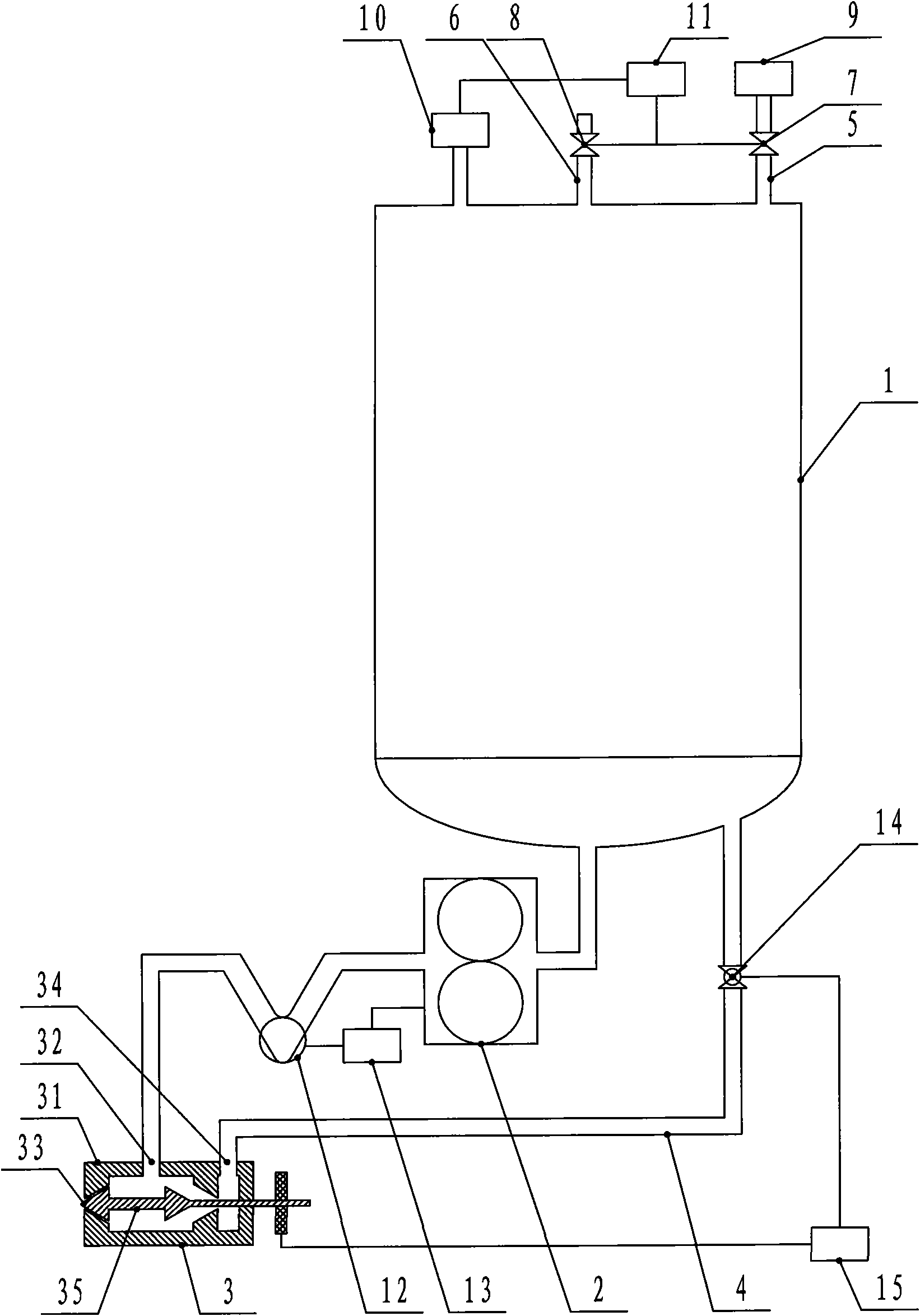
[0011] The flow control device of the present invention will be further described in detail below in conjunction with the accompanying drawings.

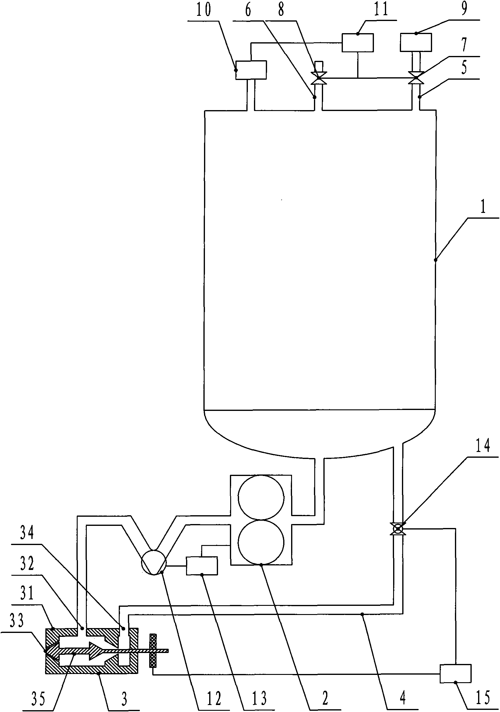
[0012] Such as figure 1 As shown, the flow control device includes a metering tank 1. The metering tank 1 is connected to the metering pump 2 through a pipeline. The metering pump 2 is connected to the pouring valve 3 through a pipeline. The pouring valve 3 is connected to the metering tank 1 through a circulation pipe 4. The pouring valve 3 includes a hollow cylindrical shell 31, the side of the shell 31 is provided with a feed port 32, one end of the shell 31 is provided with a discharge port 33, and the other end of the shell 31 is provided with a circulation Port 34, and the inside of the housing 31 is provided with a pouring rod 35. When the pouring rod 35 moves telescopically, the feed port 32 communicates with the circulation port 34 or the discharge port 33 respectively, and the circulation pipe 4 and the pouring valve 3 Ci...


PUM


Abstract

The invention relates to a flow control device, comprising a metering tank, wherein the metering tank is connected with a metering pump via a pipeline; the metering pump is connected with a pouring valve via a pipeline; the pouring valve is connected with the metering tank via a circulating tube; the metering tank is provided with an air inlet pipe and an air outlet pipe; the air inlet pipe is provided with an air intake valve and the air outlet pipe is provided with an air outlet valve; the air inlet pipe is connected with an air source; the metering tank is connected with a pressure sensor via a pipeline; the pressure sensor is in communicated connection with a pressure controller; the pressure controller is in communicated connection with the air inlet and outlet valves; a mass flow meter is arranged on the pipeline between the metering pump and the pouring valve; the mass flow meter is in communicated connection with a rotary speed controller; the rotary speed controller is in communicated connection with the metering pump; the circulating tube is provided with a shutoff valve; the pouring valve is in communicated connection with a shutoff controller; and the shutoff controller is in communicated connection with the shutoff valve. The invention can accurately control the flow of fluid materials.

Description

technical field [0001] The invention relates to the technical field of metering equipment, in particular to a flow control device. Background technique [0002] The flow control device is a device used to control the size of the flow. In production, the accuracy of flow control directly affects the accuracy of products. The structure of the existing flow control device is: including a metering tank, the metering tank is connected to the metering pump through the pipeline, the metering pump is connected to the pouring valve through the pipeline, and the pouring valve is connected to the metering tank through the circulation pipe. The pouring valve consists of a hollow cylindrical shell, the side of the shell is provided with a feed port, one end of the shell is provided with a discharge port, the other end of the shell is provided with a circulation port, and the inside of the shell is provided with a pouring rod. When the pouring rod moves telescopically, the feed port is ...

Claims


Application Information

Patent Timeline
Patent Type & Authority Applications(China)
IPC IPC(8): G05D7/06G01F1/76
Inventor 李敏超承黎明陆红彪陈海风张东芝
Owner 奥斯汀新材料(张家港)有限公司
Learn More