Heat exchange device

A technology of heat exchange devices and heat exchange tubes, which is applied in the types of heat exchangers, indirect heat exchangers, lighting and heating equipment, etc., can solve the problem of complex structure and processing technology of heat exchange devices, which are difficult to popularize and apply on a large scale, Limitation of application range and other issues, to achieve the effect of improving heat exchange efficiency and heat exchange speed, reducing material and manufacturing costs, and ensuring safety and reliability

Inactive Publication Date: 2010-10-27
谷东照
View PDF0 Cites 2 Cited by
  • Summary
  • Abstract
  • Description
  • Claims
  • Application Information

AI Technical Summary

Problems solved by technology

[0004] In the existing heat exchange device of this type, the inlet and outlet nozzles of the working fluid are respectively opened at the bottom and top of the container, or at the upper and lower ends of both sides of the container, and the inlet and outlet nozzles of the heat exchange gas or liquid are also respectively opened at the bottom and top of the container. The bottom and top of the container, or the upper and lower ends on both sides of the container, and the inlet and outlet nozzles of the working fluid and the inlet and outlet nozzles of the heat exchange gas or liquid are respectively opened on different walls of the container, so that the structure of the heat exchange device and The processing technology is complex, the cost increases, the reliability decreases, and the application range is also greatly limited. It is only suitable for industrial environments or large-scale refrigeration industries, and it is difficult to achieve large-scale promotion and application.

Method used


Image

  • Heat exchange device
  • Heat exchange device

Examples


Embodiment Construction

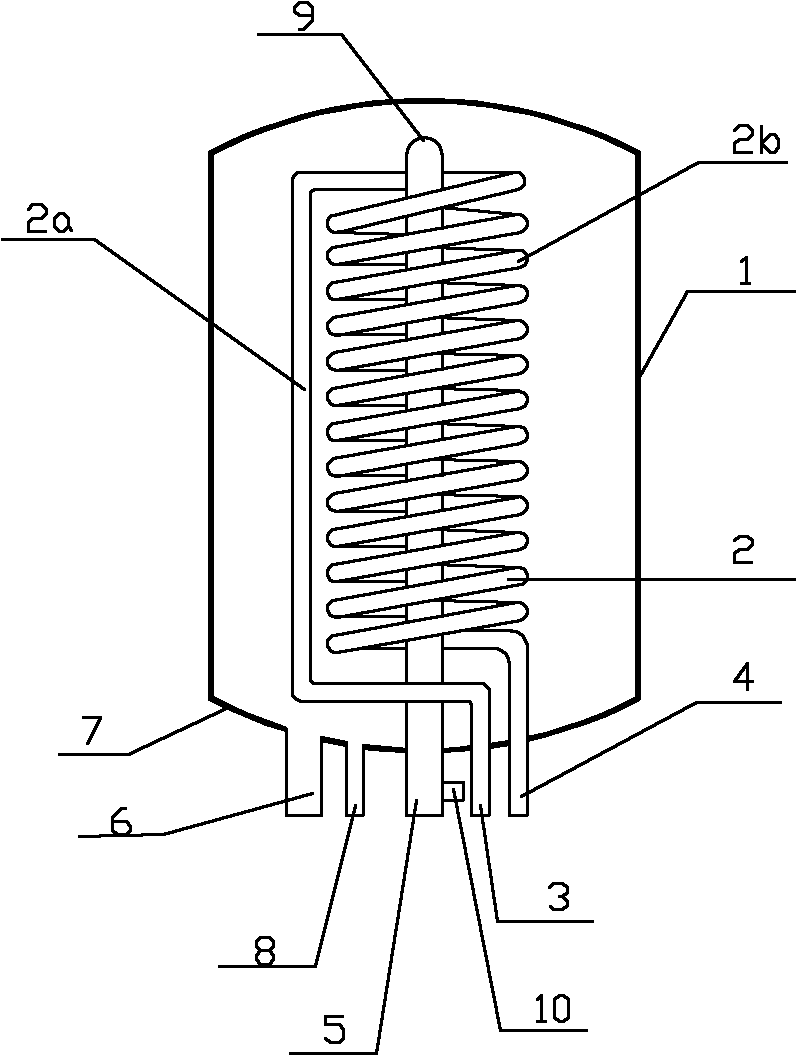
[0019] Below in conjunction with accompanying drawing and specific embodiment the present invention is described in further detail:

[0020] like figure 1 As shown, a heat exchange device includes a closed container 1, and a heat exchange module 2 is arranged in the container 1, and a high-temperature or low-temperature working fluid flows in the heat exchange module 2, which is used to exchange heat with the container 1 The liquid or gas performs heat exchange. The two ends of the heat exchange module 2 are respectively connected to the first tube 3 of the working medium and the second tube 4 of the working medium. The container 1 is fixedly connected with the first heat exchange tube 5 and the second heat exchange tube 6. The first heat exchange tube 5 and the second heat exchange tube 6 are used for inflow or outflow of heat exchange liquid or gas.

[0021] In this device, the first working medium tube 3, the second working medium tube 4, the first heat exchange tube 5 and...


PUM


Abstract

The invention relates to a heat exchange device, which comprises a closed container. A heat exchange module is arranged in the container; two ends of the heat exchange module are connected with a first working substance pipe and a second working substance pipe respectively; a first heat exchange pipe and a second heat exchange pipe are fixedly connected on the container; the first working substance pipe, the second working substance pipe, the first heat exchange pipe and the second heat exchange pipe are all fixedly connected on the bottom wall of the container; a top opening of the second heat exchange pipe is directly formed on the bottom wall of the container and communicated with the cavity of the container; and the first heat exchange pipe passes through the bottom wall of the container and extends to the interior of the container. All pipes of the device are fixedly connected at the bottom of the container so that the integral structure of the heat exchange device is simpler; meanwhile, the heat exchange device simplifies the machining process, greatly reduces the material and manufacturing costs, and can improve the reliability; in addition, by adjusting the height of the first heat exchange pipe, effective demixing of heat exchange liquid or gas in the container can be realized so as to obtain liquid or gas with different temperatures and improve the heat exchange efficiency of the whole device.

Description

technical field [0001] The invention relates to a heat exchange device, in particular to a heat exchange device which can be widely used for gas-gas, liquid-liquid or gas-liquid heat exchange. Background technique [0002] In the petrochemical industry, boilers, water heaters, air-conditioning chillers, heat pump water heaters and hot water air conditioners, heat exchange devices for gas-gas, liquid-liquid and gas-liquid heat exchange are used. The heat exchange devices have different structures according to their uses. will vary. [0003] Among them, the structure of the more commonly used heat exchange device generally includes a closed container, and a heat exchange module is arranged in the container. The inlet liquid (gas) pipe and the liquid (gas) outlet pipe, the heat exchange gas or liquid enters the container from the liquid (gas) pipe, and performs heat exchange with the working medium in the heat exchange module, so that the heat exchange gas or liquid Heat up o...

Claims


Application Information

Patent Timeline
Patent Type & Authority Applications(China)
IPC IPC(8): F28D1/06
Inventor 谷东照
Owner 谷东照
Why Eureka
Try Eureka