Magnetic check valve

A check valve and magnetic technology, applied in the field of magnetic check valve, can solve the problems of inability to be directly applied, unable to guarantee the automatic re-suction of the valve plate and the valve core, small suction force, etc., to achieve low cost, stable and good guiding effect, The effect of good sealing performance

Inactive Publication Date: 2012-09-26
XIAMEN SOLEX HIGH TECH IND CO LTD
View PDF1 Cites 0 Cited by
  • Summary
  • Abstract
  • Description
  • Claims
  • Application Information

AI Technical Summary

Problems solved by technology

This utility model has the following deficiencies: 1. The valve plate and the valve core are sealed and sucked together by the magnetic suction force, and the valve plate is separated from the valve core by the pressure difference at both ends in the valve body. The size of the relative distance between them is inversely proportional, so when the pressure at both ends of the valve body is too large, it can impact the valve plate to make the relative distance between the valve core and the valve core too large, and the excessive relative distance makes the valve plate and the valve core The suction between them is small, and the small suction cannot ensure that the valve plate and the valve core are automatically re-attached together; 2. It is used in refrigeration equipment and cannot be directly applied to the field of bathing and faucet

Method used


Image

  • Magnetic check valve
  • Magnetic check valve
  • Magnetic check valve

Examples


Embodiment Construction

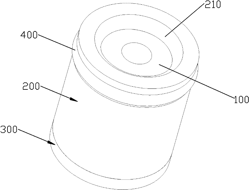
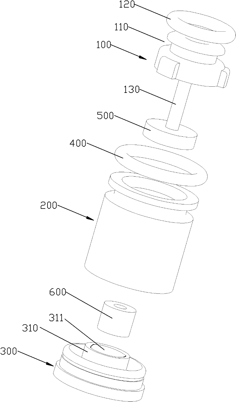
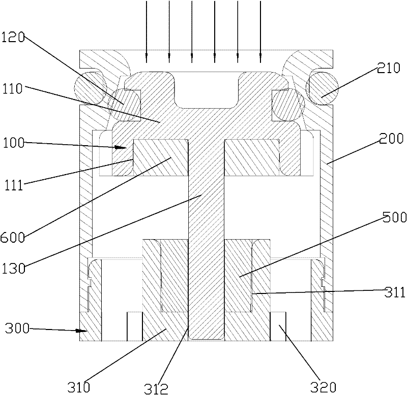
[0037] Please check Figure 1 to Figure 5 , a magnetic check valve, which includes a fixed unit and a spool 100.

[0038] The fixing unit includes a valve body 200 , a valve seat 300 and an outer sealing ring 400 . The outer sealing ring 400 is sleeved on the outer rotating surface of the valve body 200 . The tail of the valve body 200 is concavely provided with a card slot on the inner turning surface, and the outer turning surface of the valve seat 300 is provided with a card edge, and the card edge and the card slot are fitted together to lock the valve body. 200 and valve seat 300 are affixed together. In this embodiment, the valve body 200 and the valve seat 300 form a water inlet channel, the head of the valve body 200 becomes the water inlet end of the water inlet channel, and the valve seat 300 becomes the water inlet channel. Outlet. The inner rotary surface of the valve body 200 is provided with an annular flange 210 protruding inward. The annular flange 210 has ...


PUM


Abstract

The invention discloses a magnetic check valve which comprises a fixed unit and a valve core, wherein a water inlet channel is arranged in the fixed unit; the valve core is connected to the inside of the fixed unit slidably and slides between a first position and a second position; when the valve core is in the first position, the water inlet channel is in the blocking state, and when the valvecore is not in the first position, the water inlet channel is in a conducting state; the fixed unit is fixedly provided with a first magnet, the valve core is fixedly provided with a second magnet, the first magnet and the second magnet repel each other and generate repulsive force, and the direction of the repulsive force coincides with the sliding direction of the valve core; when water flows downstream, the impact force of the water flow acts on the valve core to overcome the repulsive force, so that the valve core moves to the second position from the first position and the water inlet channel is in the conducting state; and when the water flows backwards or stops, under the action of the repulsive force, the valve core moves to the first position from a non-first position, and the water inlet channel is in a blocking state. The invention can completely avoid failure of resetting.

Description

technical field [0001] The invention relates to a magnetic check valve, in particular to a magnetic check valve used in the field of bathing and faucets. Background technique [0002] A traditional check valve used in the field of bathing and faucets includes a valve body, a valve core and a spring mechanism. A water inlet channel is arranged in the valve body, and the water inlet channel has a water inlet end and a water outlet end. The spool is slidably connected in the fixed unit and slides between the first position and the second position. When the spool is in the first position, the water inlet channel is blocked. In the first position, the water inlet channel is in a conducting state. The spring mechanism is arranged inside the valve body and the valve core, and generates an elastic force, and the elastic force can act on the valve core to make the valve core be in the first position. The traditional check valve is equipped with a spring mechanism, which has a comp...

Claims


Application Information

Patent Timeline
Patent Type & Authority Patents(China)
IPC IPC(8): F16K15/02F16K1/36F16K1/42F16K27/02
CPCF16K15/06F16K31/084
Inventor 黄祥陈添育曹斌周华松
Owner XIAMEN SOLEX HIGH TECH IND CO LTD
Why Eureka
Try Eureka