Magnetic tensile machine

A tensioner and magnetic technology, applied in the direction of wind power engine, machine/engine, wind power motor combination, etc., can solve problems such as no satisfactory technical solutions, no mature products, etc., achieve simple structure, improve power generation efficiency, and reduce costs Effect

Inactive Publication Date: 2013-03-13
刘新广
View PDF4 Cites 0 Cited by
  • Summary
  • Abstract
  • Description
  • Claims
  • Application Information

AI Technical Summary

Problems solved by technology

However, there is no relatively satisfactory technical solution and almost no mature products for overcoming the horizontal (axial) impact force generated by the wind on the bearing through the fan impeller 1 and the rotating shaft 2.

Method used


Image

  • Magnetic tensile machine

Examples


Embodiment 1

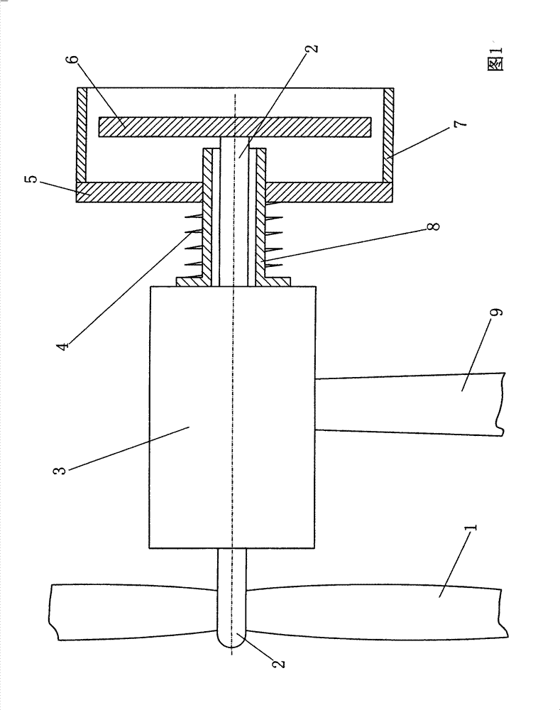
[0014] Embodiment 1: as shown in Figure 1. Described magnetic puller is constituted like this: from the non-magnetic sleeve 8 on the left side band edge of coaxial sleeve left side of the rotating shaft 2 tail (right) end of generator 3, the inner circle of non-magnetic sleeve 8 does not contact the outer circle of shaft 2, non-magnetic The left end surface of the sleeve 8 is connected with the right end surface of the stator of the generator 3 or other static structural parts, and the right end surface of the shaft 2 protrudes from the right end surface of the non-magnetic sleeve 8; , the middle hole of the magnetic circular plate 5 and the small outer circle of the non-magnetic sleeve 8 form a sliding fit, and the left end of the tension spring 4 is connected with the surface of the non-magnetic sleeve 8 or the right end of the stator of the generator 3 or other static structural parts 1. The right end of the tension spring 4 is connected with the left end face of the magnet...


PUM


Abstract

The invention relates to a magnetic tensile machine. A nonmagnetic sleeve with an edge at the left is coaxially sleeved from the tail end of a rotating shaft of an electric generator; the inner circle of the nonmagnetic sleeve does not contact the outer circle of the shaft; the left end face of the nonmagnetic sleeve is connected with the right end face of a stator of the electric generator or any other static structural members; and the right end of the shaft protrudes out of the right end face of the nonmagnetic sleeve; a tension spring is sleeved outside the small outer circle of the nonmagnetic sleeve; a middle hole of a magnetic circular plate and the small outer circle of the nonmagnetic sleeve form a slide fit; the left end of the tension spring is connected with the end face of the nonmagnetic sleeve or the right end face of the electric generator or any other static structural members; the right end of the tension spring is connected with the right end face of the magnetic circular plate; the right end of the rotating shaft is coaxially connected with a magnetic disc; the magnetic disc is an axial distance away from the magnetic circular plate; and the magnetic circular plate and the magnetic disc can generate a magnetic tension. The magnetic tensile machine can prolong the service life of a bearing, enhance the generating efficiency of a windmill generator, reduce the wind speed for starting, and prolong the service life of a generator bearing.

Description

technical field [0001] The invention relates to a magnetic device, in particular to a magnetic puller. Background technique [0002] Most of the existing wind generators are horizontal shaft type, and their bearings are traditional mechanical contact rolling or sliding bearings. The force on the shaft of the horizontal-axis wind turbine is much worse than that of the general-purpose horizontal-axis generator. The bearings of general-purpose horizontal-axis generators mainly support the gravity of the rotor shaft and resist radial disturbances to make the shaft centered, while the shafts of horizontal-axis wind turbines are subject to two serious forces in addition to gravity and radial disturbances. Effects: the one is the gravity effect of the fan impeller 1 (as shown in Figure 1 ) installed on the extended end of the shaft 2, and the second is to withstand the impact force of the wind on the horizontal direction of the fan impeller. The gravity of the fan impeller 1 make...

Claims


Application Information

Patent Timeline
Patent Type & Authority Patents(China)
IPC IPC(8): F03D9/00
CPCY02E10/725Y02E10/72
Inventor 刘新广
Owner 刘新广
Why Eureka
Try Eureka