
Thin type speaker magnetic circuit

A loudspeaker and thin technology, applied in the field of electroacoustics, can solve problems such as large distortion, affecting product quality, and magnetic flux leakage, and achieve the effects of reasonable overall thickness, improved stability, and enhanced reliability

Inactive Publication Date: 2010-10-20
WUXI JIEFU ELECTROACOUSTIC
View PDF4 Cites 3 Cited by
  • Summary
  • Abstract
  • Description
  • Claims
  • Application Information

AI Technical Summary

Problems solved by technology

There is also a U-shaped magnetic yoke directly removed to form an open magnetic circuit. Although this open magnetic circuit structure solves the problem of high thickness, it has the defects of large distortion and serious magnetic flux leakage, which seriously affects the quality of the product. quality

Method used


Image

  • Thin type speaker magnetic circuit
  • Thin type speaker magnetic circuit
  • Thin type speaker magnetic circuit

Examples


Embodiment Construction

[0018] The present invention will be further described below in conjunction with specific drawings and embodiments.

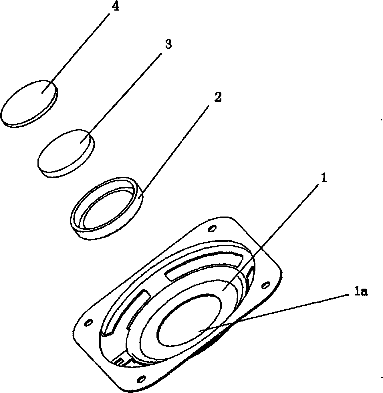
[0019] As shown in the figure, the thin loudspeaker magnetic circuit in the embodiment is mainly composed of a pot frame 1 , a U-shaped magnetic yoke 2 , a magnet 3 and a magnetic pole core 4 .

[0020] Such as Figure 1 ~ Figure 3 As shown, the center of the bottom of the pot frame 1 has a middle hole 1a, and the U-shaped magnetic yoke 2 is installed in the middle hole 1a, and the U-shaped magnetic yoke 2 and the middle hole 1a at the bottom of the pot frame 1 are tightly combined by interference fit , the bottom surface of the U-shaped magnetic yoke 2 is in the same plane as the bottom surface of the basin frame 1 . The magnet 3 and the magnetic pole core 4 are installed in the U-shaped magnetic yoke 2, the lower surface of the magnet 3 is closely combined with the inner surface of the bottom of the U-shaped magnetic yoke 2, and the upper surface of the magn...


PUM


Abstract

The invention relates to a thin type speaker magnetic circuit. According to the technical scheme provided by the invention, the thin type speaker magnetic circuit comprises a basin frame, a U-shaped magnetic yoke, a magnet and a magnetic pole core, wherein the magnet and the magnetic core are arranged inside the U-shaped magnetic yoke, the lower surface of the magnet is tightly combined with the inner surface of the bottom of the U-shaped magnetic yoke, the upper surface of the magnet is tightly combined with the magnetic pole core, and a certain magnetic gap is reserved between the outer walls of the magnet and the magnetic pole core and the inner wall of the U-shaped magnetic yoke. The thin type speaker magnetic circuit is characterized in that a center hole is arranged on the center of the bottom of the basin frame, the U-shaped magnetic yoke is arranged in the center hole, and the bottom surface of the U-shaped magnetic yoke and the bottom surface of the basin frame are positioned on the same plane. The invention has skillful and reasonable structure and effectively reduces the total height of the speaker magnetic circuit without reducing the magnetic flux and the BL value, and overlarge heat energy cannot be caused by cutting magnetic lines of force by a voice coil in an alternating magnetic field so as to ensure the acoustic performance and the reliability of the speaker product.

Description

technical field [0001] The invention belongs to the technical field of electroacoustics, and relates to a loudspeaker magnetic circuit structure, in particular to a thin loudspeaker magnetic circuit. Background technique [0002] In the prior art, the magnetic circuit structure of speakers used in flat panel TVs such as LCD and PDP is generally a U-shaped magnetic yoke arranged at the bottom of the frame and protruding downward. Suitable for new ultra-thin flat panel TV applications. There is also a U-shaped magnetic yoke directly removed to form an open magnetic circuit. Although this open magnetic circuit structure solves the problem of high thickness, it has the defects of large distortion and serious magnetic flux leakage, which seriously affects the quality of the product. quality. [0003] Therefore, it is necessary to design a thin loudspeaker magnetic circuit structure. By changing the mutual position of the U-shaped magnetic yoke and the pot frame, the overall hei...

Claims


Application Information

Patent Timeline
Patent Type & Authority Applications(China)
IPC IPC(8): H04R9/02H04R9/06
Inventor 蒋加星叶卫华
Owner WUXI JIEFU ELECTROACOUSTIC
Learn More