
Capacitance sensor calibration system for measuring very fast transient overvoltage (VFTO)

A capacitive sensor, transient overvoltage technology, applied in the measurement of electrical variables, voltage/current isolation, measurement devices, etc., can solve problems such as the amplitude and steepness are very different, the voltage is not high enough, and the response time of VFTO cannot be satisfied. , to achieve the effect of good test repeatability and less impact

Active Publication Date: 2013-01-02
XI AN JIAOTONG UNIV +3
View PDF0 Cites 0 Cited by
  • Summary
  • Abstract
  • Description
  • Claims
  • Application Information

AI Technical Summary

Problems solved by technology

[0004] However, at present, the voltage generated by the steep pulse generator in the capacitive sensor calibration system for VFTO measurement is not high enough and the steepness is not high enough to simulate the environment where VFTO occurs
Moreover, the existing calibration system does not use gas-insulated metal-enclosed switchgear (GIS, Gas Insulated Switchgear), and there must be GIS knife switch operation in the actual system. The existing technology only uses a steep pulse generator to simulate the GIS knife The pulse waveform generated by the gate operation is far from the actual system in amplitude and steepness
Therefore, the capacitive sensors calibrated in the low-voltage environment in the prior art cannot be applied to the actual high-voltage system, and the capacitive sensors calibrated in this way cannot meet the requirements of VFTO response time

Method used


Image

  • Capacitance sensor calibration system for measuring very fast transient overvoltage (VFTO)
  • Capacitance sensor calibration system for measuring very fast transient overvoltage (VFTO)
  • Capacitance sensor calibration system for measuring very fast transient overvoltage (VFTO)

Examples


Embodiment Construction

[0031] In order to enable those skilled in the art to better understand and implement the present invention, several technical terms are introduced below.

[0032] High-voltage steep pulse generator: a pulse voltage source with a small rise time (preferably 3 ns in the embodiment of the present invention), and a half-peak width that meets certain requirements (approximately 100 ns in the embodiment of the present invention).

[0033] Conical transmission cylinder: a transmission line with variable radius, the wave impedance of which can gradually change (variable impedance line) or remain unchanged (equal impedance line is used in the embodiment of the present invention, that is, remains constant).

[0034] In order to make the above objects, features and advantages of the present invention more comprehensible, specific implementations of the present invention will be described in detail below in conjunction with the accompanying drawings.

[0035] see figure 2 , which is a ...


PUM


Abstract

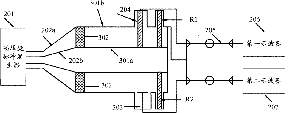
A capacitive sensor calibration system for measuring fast transient over-voltages is provided. The system includes: a high voltage steep pulse generator (201), a conical transmission tube (202), a capacitive sensor (203), a resistive voltage divider (204), coaxial cables (205-1, 205-2), a first oscilloscope (206) and a second oscilloscope (207). The high voltage steep pulse generator (201) is arranged to generate a high voltage steep pulse. The high voltage steep pulse is transmitted to the capacitive sensor (203) and the resistive voltage divider (204), which are installed on a Gas Insulation metal closed Switchgear (GIS) through the conical transmission tube (202). The conical transmission tube (202) is connected with the GIS coaxially. The resistive voltage divider (204) transmits a resistive voltage dividing signal to the first oscilloscope (206) through the coaxial cable (205-1). The capacitive sensor (203) transmits a capacitive voltage dividing signal to the second oscilloscope (207) through the coaxial cable (205-2). The calibration system utilizes the high voltage steep pulse generator (201) as the signal resource, so as to accord with a real wave shape of a Very Fast Transient Over-voltage (VFTO). The capacitive sensor (203) and the resistive voltage divider (204) are installed on the GIS tube, so as to calibrate the capacitive sensor (203) under the state approaching to the real installing condition.

Description

technical field [0001] The invention relates to the technical field of capacitive sensors, in particular to a capacitive sensor calibration system for fast transient overvoltage measurement. Background technique [0002] The capacitive sensor calibration system for VFTO (Very Fast Transient Over-voltage) measurement is to detect whether the performance of the capacitive sensor meets the requirements and determine the voltage division ratio of the capacitive sensor. [0003] The existing calibration system of capacitive sensor commonly used for VFTO measurement is as follows: figure 1 As shown, a steep pulse generator 101 , a coaxial cable 102 , an attenuator 103 , a capacitive sensor 104 , a first oscilloscope 105 and a second oscilloscope 106 are included. Its working principle is that the steep pulse generator 101 is used as a signal source to generate voltage pulses, and the voltage pulses are transmitted to the attenuator 103 and the capacitance sensor 104 through the c...

Claims


Application Information

Patent Timeline
Patent Type & Authority Patents(China)
IPC IPC(8): G01R35/00G01R19/165
CPCG01R15/16G01R35/005G01R31/312
Inventor 丁卫东王绍武李志兵孙凤举李峰马宾张乔根
Owner XI AN JIAOTONG UNIV
Learn More