New method for automatically measuring screw pitch of propeller blades

An automatic measurement and propeller technology, applied in measurement devices, instruments, optical devices, etc., can solve the problems of time-consuming and laborious measurement process, wear measurement, errors, etc., and achieve the effect of convenient automatic measurement, reduction of production cost, and shortening of processing cycle.

Inactive Publication Date: 2010-10-20
陆金桂
View PDF0 Cites 10 Cited by
  • Summary
  • Abstract
  • Description
  • Claims
  • Application Information

AI Technical Summary

Problems solved by technology

Among them, the pole coordinate measuring machine and the three-coordinate measuring machine are commonly used coordinate measuring machine equipment for propellers. These measuring machines are huge in size. Generally, the coordinates of the blade measurement points are obtained by directly contacting the propeller blade with the measuring rod and probe. Since the propeller contains multiple blades, it is necessary to perform point-by-point coordinate measurement on different measurement sections of each blade during the manufacturing process of the propeller. The measurement process is time-consuming and laborious, which seriously affects the efficiency of the measurement and cannot realize automatic measurement.
In addition, the measuring head of the existing coordinate measuring machine needs to contact the metal surface of the blade, and the wear caused by long-term use will also cause measurement errors
Therefore, the above factors affect the accurate measurement of the propeller blades by the existing coordinate measuring machine. At the same time, with the improvement of the automation level of the modern production process, the method of using the measuring machine to measure the pitch can no longer meet the needs of the modern production of the propeller. A fast, Accurate and automated propeller pitch measurement method is of great significance

Method used


Image

  • New method for automatically measuring screw pitch of propeller blades
  • New method for automatically measuring screw pitch of propeller blades
  • New method for automatically measuring screw pitch of propeller blades

Examples


Embodiment Construction

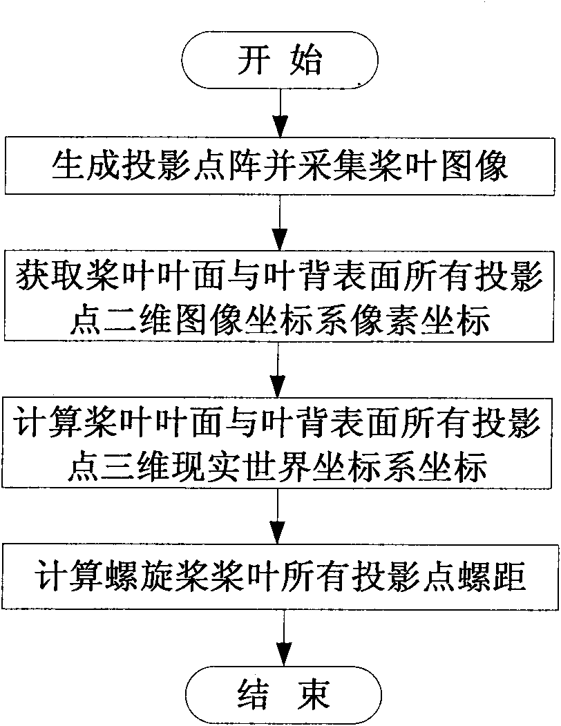
[0023] Below in conjunction with accompanying drawing, illustrate the new method that the present invention proposes based on the propeller blade pitch automatic measurement of image method, its technical principle and specific implementation method are as follows:

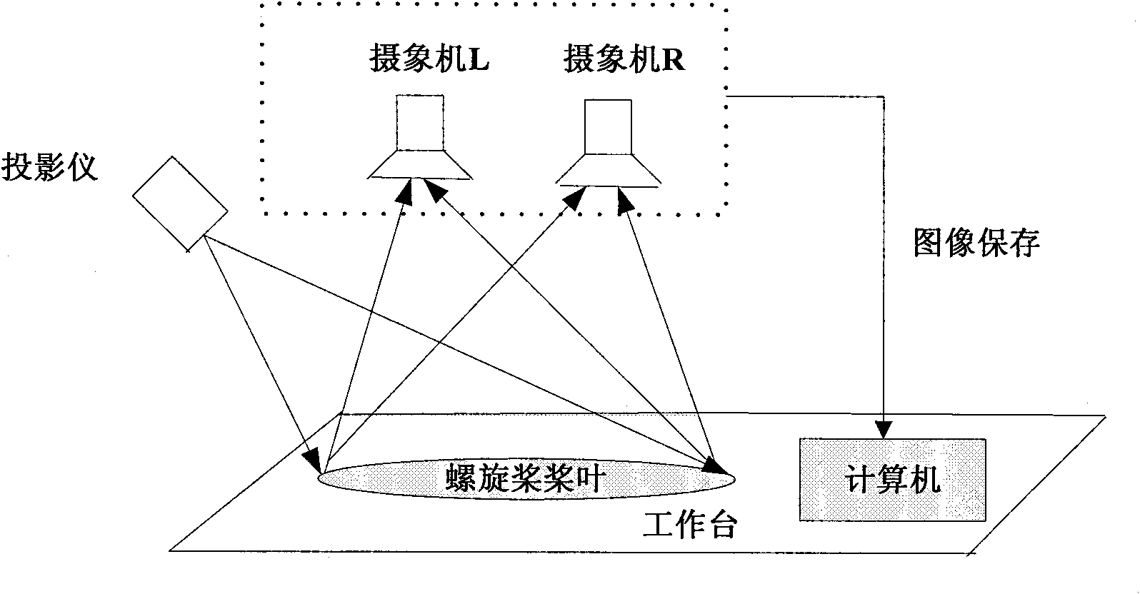
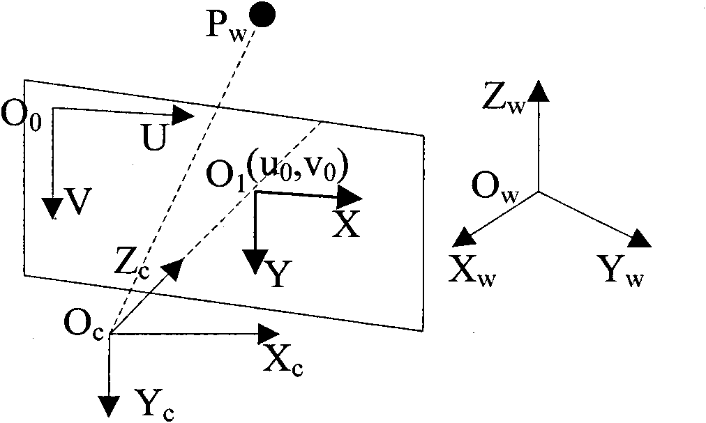
[0024] figure 1 It is the main step of the automatic measurement method of propeller blade pitch. This method is measured by image. First, the projection dot matrix is ​​generated by computer programming and projected on the surface of the propeller and the image is collected, and then all the projection points on the blade surface and the back surface of the blade are obtained. The pixel coordinates of the two-dimensional image coordinate system, and calculate the three-dimensional real-world coordinate system coordinates of all projection points according to the binocular vision theory, based on which the three-dimensional coordinate model of the propeller blade is constructed and the weight of the blade is calcu...


PUM


Abstract

The invention provides a new method for automatically measuring the screw pitch of propeller blades, which takes an image as a basis to carry out non-contact automatic measurement of the screw pitch of the propeller blades. The method comprises the following steps: firstly, collecting the images of the propeller blades by utilizing equipment such as a computer, a projector, a camera and the like; acquiring a coordinate of a two-dimensional image coordinate system of all the projective points of the blades by taking a digital image processing technology as a basis; calculating a coordinate of a three-dimensional real-world coordinate system of all the projective points of the blades by utilizing a camera calibration model; and finally calculating the screw pitch of the propeller blades by utilizing the computer.

Description

Technical field: [0001] The invention belongs to the related field of propeller measurement, in particular to a new image-based non-contact automatic measurement method for propeller blade pitch. technical background: [0002] The propeller provides thrust for the ship's navigation and is a key part of the ship's propulsion system. The quality of the propeller directly affects the propulsion efficiency of the ship. In order to ensure the manufacturing quality of propellers, the State Bureau of Technical Supervision has issued national standards on the technical requirements of metal propellers, which regulate many technical indicators including the pitch of propeller blades. Therefore, in order to control the quality of the propeller during the propeller manufacturing process, it is necessary to repeatedly measure the pitch parameters of the propeller blades. The measurement of propeller blade pitch parameters can provide a basis for accurate adjustment of blade processing...

Claims


Application Information

Patent Timeline
IPC IPC(8): G01B11/14G01B11/03
Inventor 陆金桂张建德陈凤馨
Owner 陆金桂
Why Eureka
Try Eureka