Slag discharging device and pulverized coal burner using same

A pulverized coal burner and combustion chamber technology, which is applied in the direction of the burner, burner, and combustion method of burning powder fuel, can solve the problems of affecting the combustion efficiency of the pulverized coal burner, the slag removal effect is not obvious, and the operation is troublesome. Achieve the effect of high degree of automation, convenient operation and saving production cost

Inactive Publication Date: 2010-10-20
重庆市牛人科技有限公司
View PDF6 Cites 7 Cited by
  • Summary
  • Abstract
  • Description
  • Claims
  • Application Information

AI Technical Summary

Problems solved by technology

[0005] 1. Using chemical methods, specifically using various slag removers, etc. This method is costly, troublesome to operate, and the slag removal effect is not obvious;
[0006] 2. The use of physical methods mainly refers to changing the placement state of the pulverized coal burner, using gravity to make the condensed slag fall off the inner cavity wall, and then discharged through the slag discharge port, but this method still has insufficient slag removal effect Obvious defects, but also affect the combustion efficiency of pulverized coal burners

Method used


Image

  • Slag discharging device and pulverized coal burner using same
  • Slag discharging device and pulverized coal burner using same
  • Slag discharging device and pulverized coal burner using same

Examples


Embodiment Construction

[0034] Hereinafter, preferred embodiments of the present invention will be described in detail with reference to the accompanying drawings. It should be understood that the preferred embodiments are only for illustrating the present invention, but not for limiting the protection scope of the present invention.

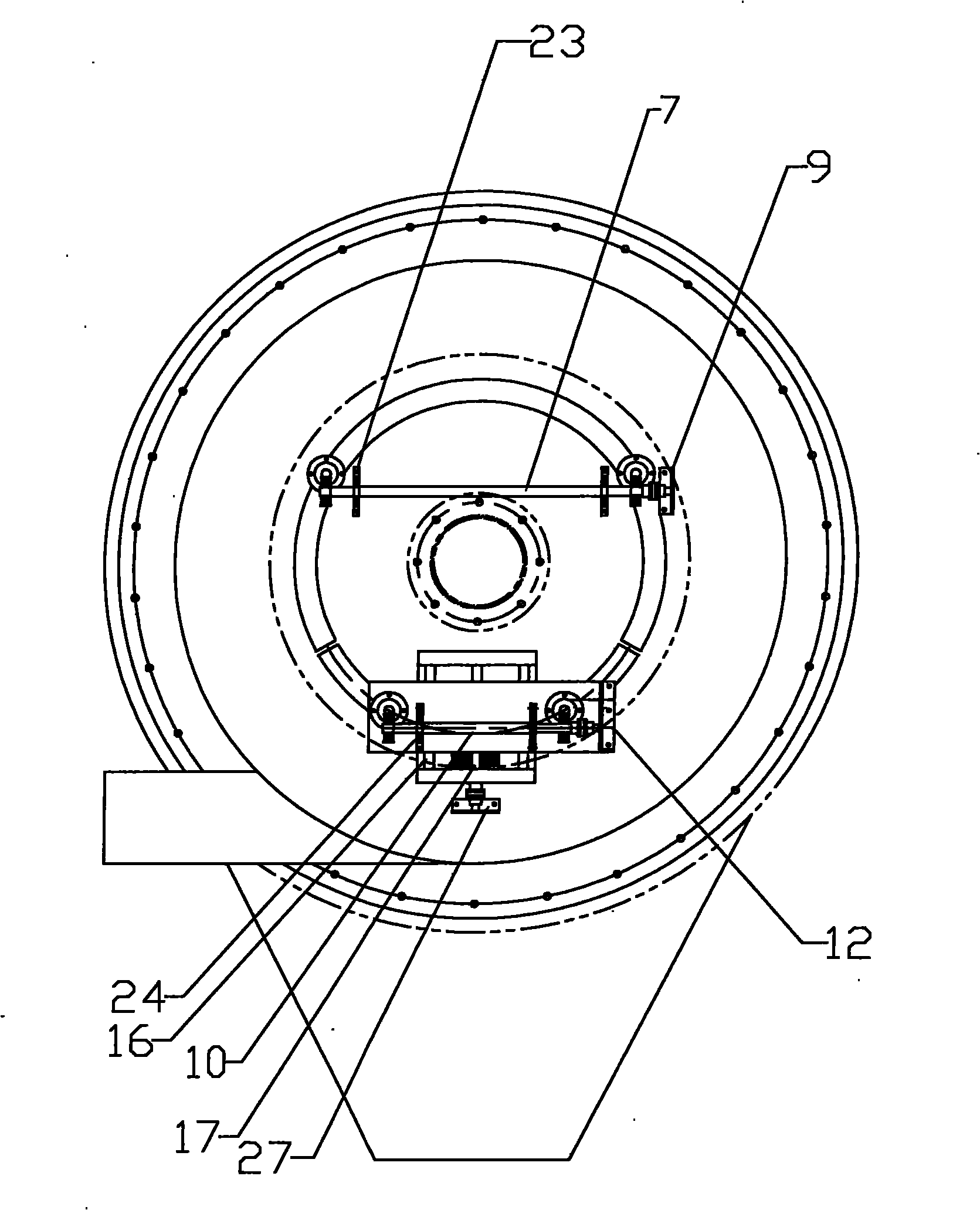
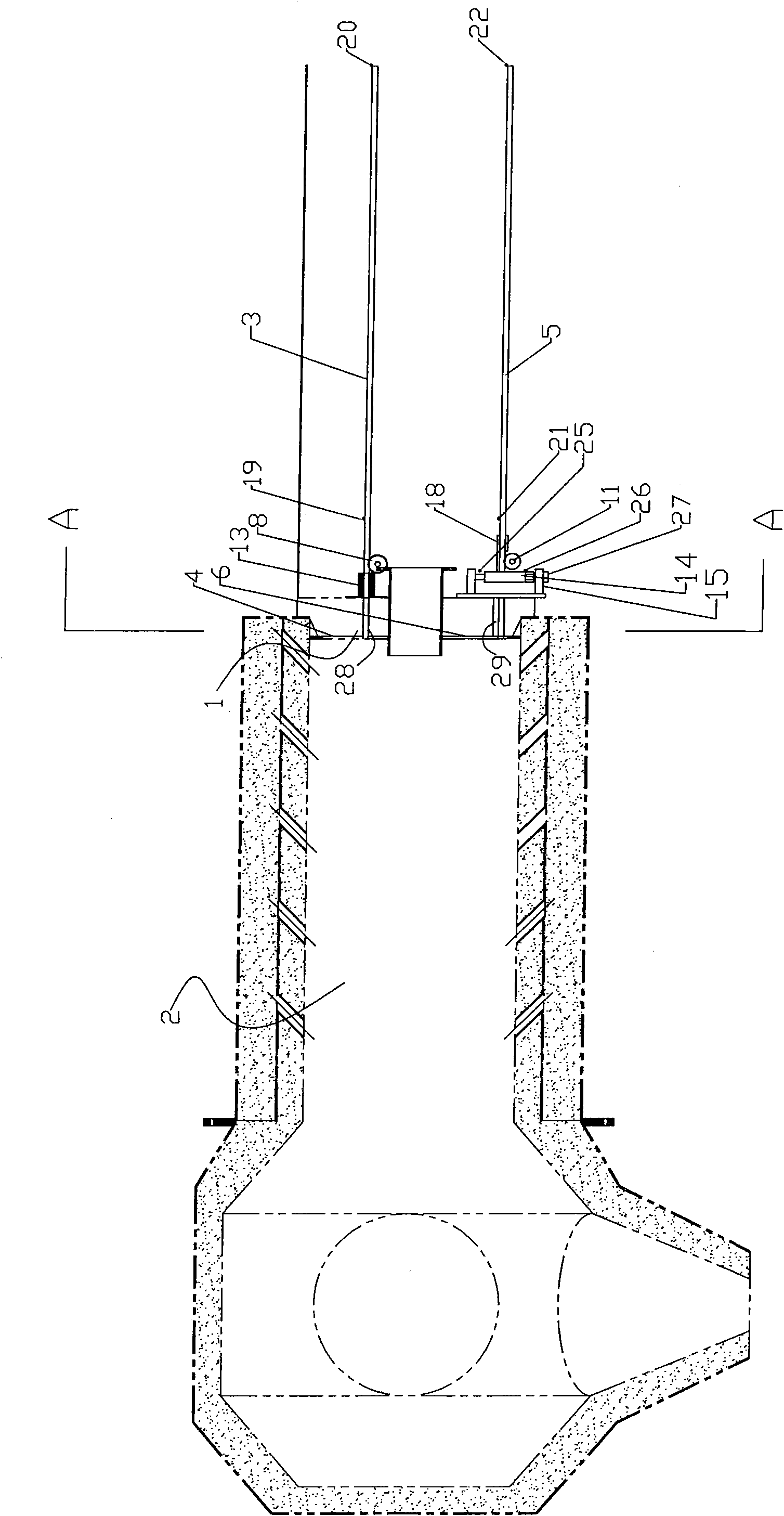
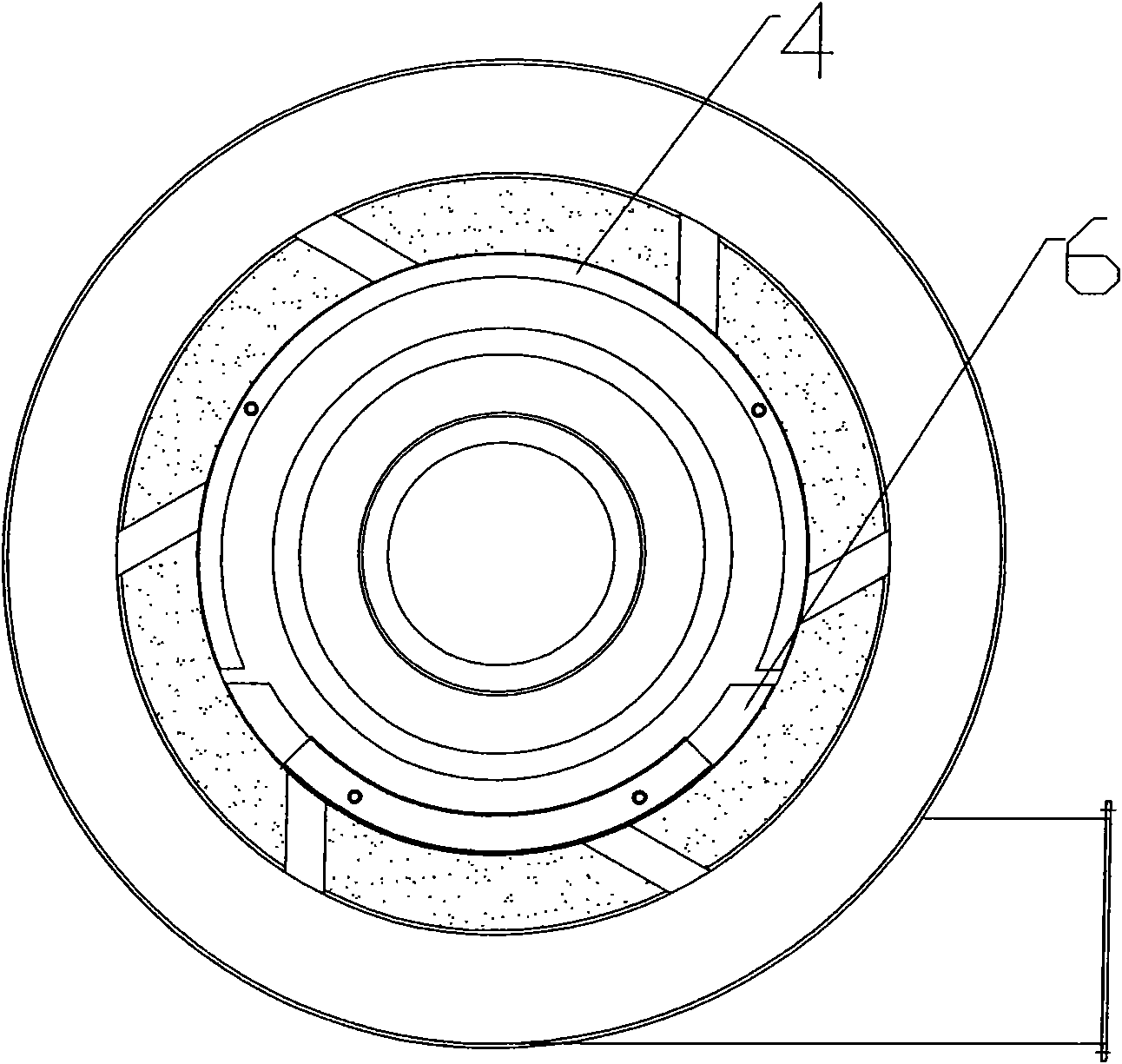
[0035] Such as Figure 1 to Figure 3 As shown, the slagging device of the present invention is used to be installed on a pulverized coal burner to realize real-time slagging, and includes an upper slagging structure and a lower slagging structure, and the upper slagging structure includes an upper push rod 3 and an upper slag pushing plate 4 And driving power unit I, the front end of the upper push rod 1 enters the interior of the combustion chamber 2 through the sliding hole I 28 arranged on the upper half of the combustion chamber door 1, and the outer edge of the upper slag pushing plate 4 is connected to the inner cavity wall of the combustion chamber The upper tr...


PUM


Abstract

The invention discloses a slag discharging device which is installed on a pulverized coal burner to realize the purpose of discharging slag in real time. The slag discharging device comprises an upper slag discharging structure and a lower slag discharging structure, wherein the upper slag discharging structure comprises an upper push rod, an upper slag pushing plate and a driving power device I, wherein the upper push rod is driven by the driving power device I to push and scrape the slag accumulated on the surface on the upper part of the inner cavity wall of a burning chamber by front-and-back reciprocating slide; and the lower slag discharging structure comprises a lower push rod, a lower slag pushing plate and a driving power device II, wherein the lower push rod is driven by the driving power device II to push the slag accumulated on the surface of the lower part of the inner cavity wall of the burning chamber to a slag outlet at the back part of the burning chamber. The slag pushing device of the invention is designed according to colloidal materials in the burning process and agglutination mode of coal slag in the cavity and fully considers different structures and characteristics of the upper cavity part and the lower cavity part; and the slag discharging device has the advantages of high slag discharging efficiency, compact integral structure and convenient operation and can ensure that coal slag in the cavity can be cleared in time, thereby effectively improving the burning efficiency of pulverized coal.

Description

technical field [0001] The invention relates to the technical field of pulverized coal combustion, in particular to a slagging device and a pulverized coal burner using the slagging device. Background technique [0002] The pulverized coal burner is the main component of the pulverized coal furnace combustion equipment. Its function is to send the pulverized coal and the air required for combustion into the furnace, and organize a reasonable airflow structure so that the fuel can be ignited quickly and burn stably. It has a multi-stage multi-nozzle air supply guide structure, which is specially designed to make coal powder generate high-temperature eddy current in a short period of time. It has the advantages of high efficiency, energy saving, complete combustion, high heat utilization rate, and is suitable for various coal powders. It can eliminate smoke and dust, improve working conditions and reduce labor intensity. It is an ideal product for energy saving and environment...

Claims


Application Information

Patent Timeline
Patent Type & Authority Applications(China)
IPC IPC(8): F23J1/06F23D1/00
Inventor 田琛苏桂从赵雷胡汉芬
Owner 重庆市牛人科技有限公司
Why Eureka
Try Eureka