
Device, system and method for correcting direct current offset

A DC offset and correction device technology, applied in the direction of DC level restoration device/bias distortion correction, baseband system components, multi-frequency modulation conversion, etc., can solve the problem of signal-to-noise ratio deterioration, slow correction speed, amplifiers Saturation and other issues, achieve low corner frequency and avoid distortion

Inactive Publication Date: 2010-10-13
广州市广晟微电子有限公司
View PDF5 Cites 4 Cited by
  • Summary
  • Abstract
  • Description
  • Claims
  • Application Information

AI Technical Summary

Problems solved by technology

On the one hand, the DC offset makes the signal-to-noise ratio worse. On the other hand, it may also cause the amplifiers at all levels after the mixer to saturate, which cannot amplify useful signals. If the DC offset enters the digital baseband, it will have a negative impact on the performance of the entire receiver system. further impact
[0004] In the prior art, it is possible to correct the DC offset by detecting the carrier leakage signal power at the output port, and then feeding it back to the input port to suppress the leakage of the local oscillator signal, but this method is not only complicated in circuit implementation, but also very slow in correction speed. Unsuitable for systems with high requirements on response time
Another way is to process it digitally. After the signal passes through the filter and amplifier circuit, the DC offset is not corrected, but it is processed in the digital circuit domain after passing through the analog-to-digital converter. However, this method is largely The dynamic range of filters and amplifiers is limited, and the processing efficiency is very low

Method used


Image

  • Device, system and method for correcting direct current offset
  • Device, system and method for correcting direct current offset
  • Device, system and method for correcting direct current offset

Examples


Embodiment Construction

[0027] The following will clearly and completely describe the technical solutions in the embodiments of the present invention with reference to the accompanying drawings in the embodiments of the present invention. Obviously, the described embodiments are only some of the embodiments of the present invention, not all of them. Based on the embodiments of the present invention, all other embodiments obtained by persons of ordinary skill in the art without making creative efforts belong to the protection scope of the present invention.

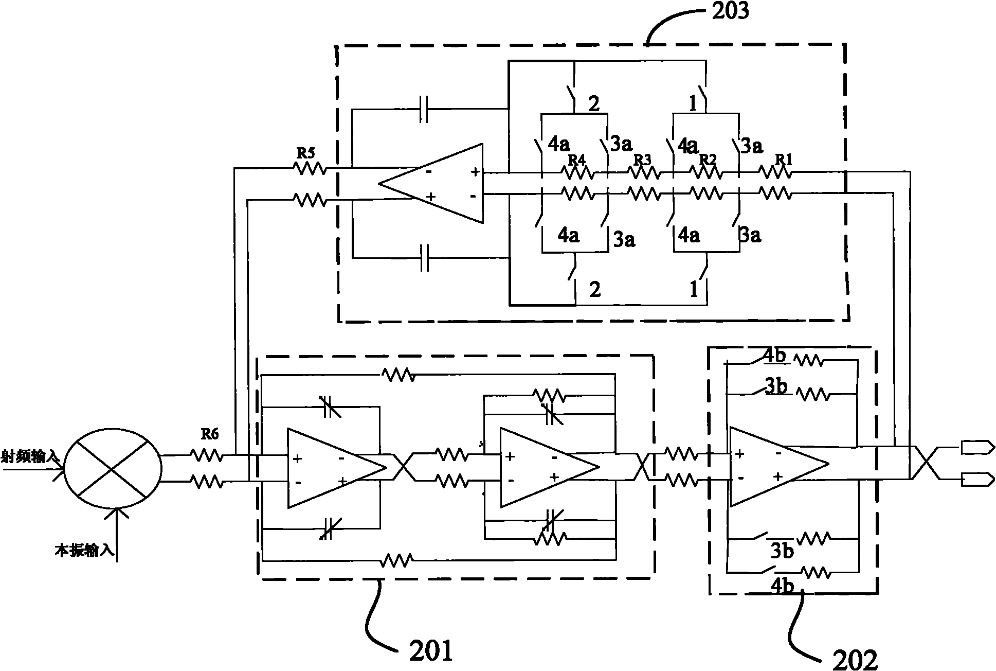
[0028] figure 1 Shown is a schematic structural diagram of a down-conversion receiver provided by the present invention, including a receiving antenna, a low-noise amplifier, a mixer, a low-pass filter unit, an amplification unit, a DC offset correction unit, an equalizer, and an analog-to-digital converter.

[0029] The function of the low-noise amplifier is to amplify the wireless signal received by the antenna, and the function of the mixer is...


PUM


Abstract

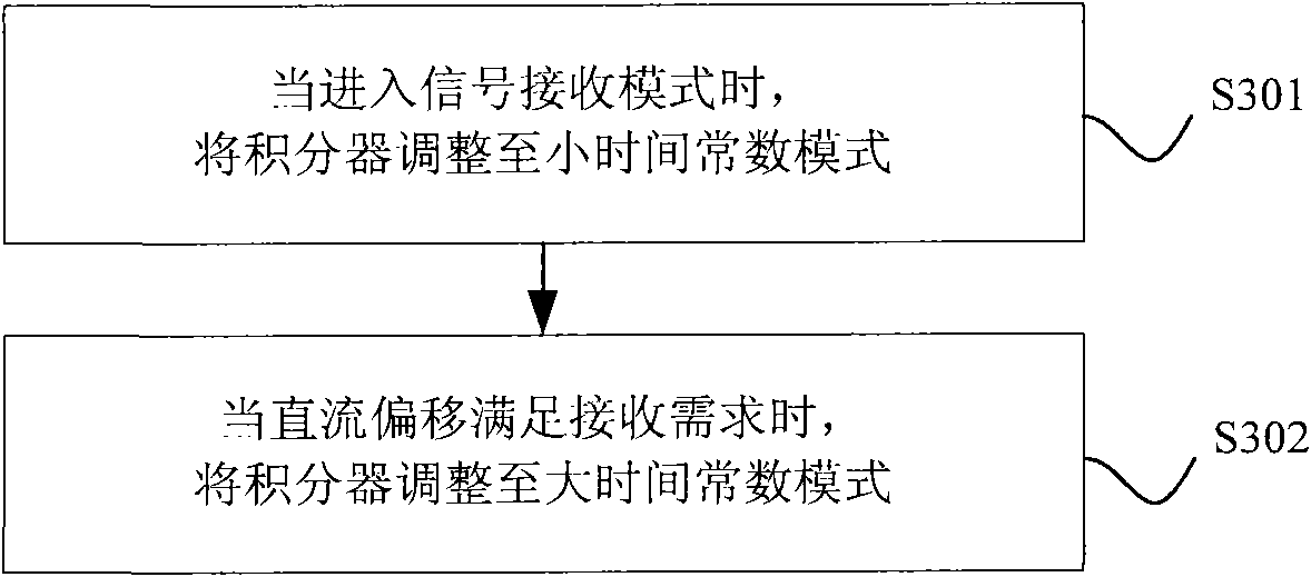
The invention discloses a device, a system, and a method for correcting direct current offset. The device for correcting direct current offset comprises a low-pass filter unit, an amplification unit and a direct current offset correcting unit, wherein the output end of the low-pass filter unit is connected with the input end of the amplification unit; and the direct current offset correcting unitcomprises an integrator which provides two kinds of time constants and performs integration on output signals of the amplification unit and feeds back the integrated signals to the input end of the low-pass filter unit. In the technical scheme provided by the invention, direct current offset of a direct down-conversion receiver can be directly corrected by using the integrator with changeable time constants, so that the technical scheme ensures that the direct current offset can be corrected to an expected value in short time when the integrator is in a small time constant model; and the integrator is regulated to a large time constant model after the correctness is finished and relatively low corner frequency is formed to avoid the distortion of the output signal.

Description

technical field [0001] The present invention relates to the technical field, in particular to a DC offset correction device, system and method. Background technique [0002] Wireless receivers currently mainly include superheterodyne structure receivers and direct down-conversion receivers. Among them, superheterodyne structure receivers have complex structures, image interference, and require high-Q and large-volume IF filters. , thus complicating the system and making integration difficult. The local oscillator of the direct down-conversion receiver is equal to the carrier frequency, and directly converts the radio frequency signal to the baseband, so there is no image interference, and no image interference suppression filter is required. The saving of IF modules can greatly simplify the system, which is beneficial to the integration of single-chip systems. At the same time, signal amplification and filtering are mainly carried out at the baseband, which reduces energy ...

Claims


Application Information

Patent Timeline
IPC IPC(8): H03D7/16H04L25/06
Inventor 梁振王昭郑卫国
Owner 广州市广晟微电子有限公司
Learn More