Micromotor commutator system

A micro-motor and subsystem technology, applied in the direction of electrical components, electromechanical devices, electric components, etc., can solve the complex assembly process of motor rectifier sub-assemblies, affect the contact area between brush and rotor commutator, commutator and coil Small and other problems, to achieve the effect of reducing assembly cost, not easy to deform, and canceling the clamping process

Inactive Publication Date: 2010-10-13
CHONGQING KNVAN ELECTRONICS
View PDF5 Cites 1 Cited by
  • Summary
  • Abstract
  • Description
  • Claims
  • Application Information

AI Technical Summary

Problems solved by technology

Since the motor and brushes are designed and manufactured in a miniaturized manner, the thickness of the parallel brushes of the brushes is ultra-thin and ultra-thin, which can easily cause deformation of the brushes during installation and use, and the distance between the two brushes cannot be guaranteed, resulting in damage. The elasticity of the brush affects the contact between the brush and the rotor commutator
[0005] The disadvantage of the prior art is: the contact area between the commutator and the coil is too small, and the glue bonding the commutator and the coil is easy to flow from the positioning port to the rotor main shaft, which reduces the overall performance of the motor
Moreover, the assembly process of the motor commutator sub-assembly composed of the rotor shaft, the fixed ring and the commutator is complex and difficult

Method used


Image

  • Micromotor commutator system
  • Micromotor commutator system
  • Micromotor commutator system

Examples


Embodiment Construction

[0039] The present invention will be described in further detail below in conjunction with the accompanying drawings and specific embodiments.

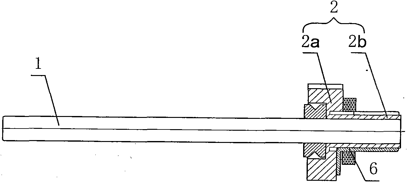
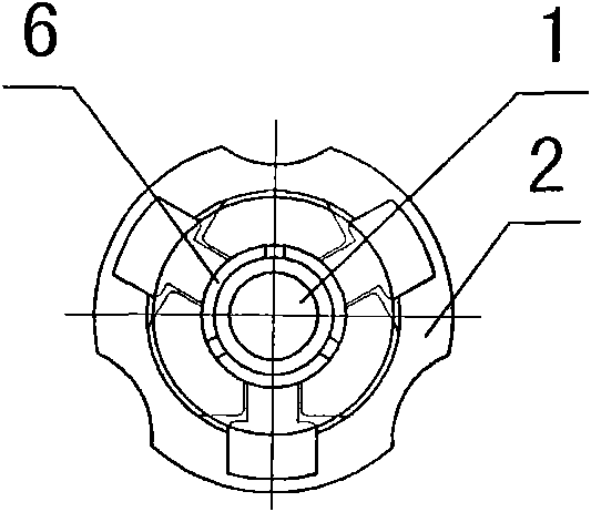
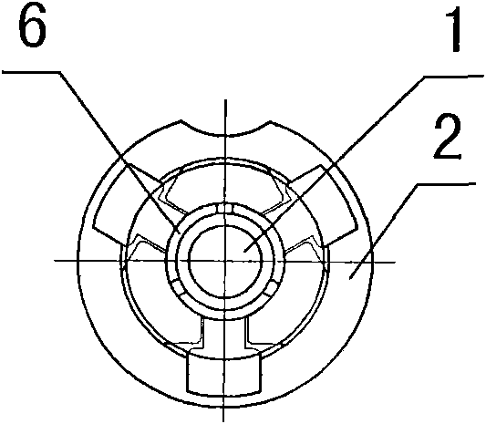
[0040] Such as Figure 4 , 5 Shown: a micro-motor rectifier subsystem, including a main shaft 1 and a commutator 2, the commutator 2 is provided with a large-diameter section 2a and a small-diameter section 2b, wherein the large-diameter section 2a is bonded to the inner wall of the coil 5 Together, three conductive sheets 6 are evenly fixed on the outer wall of the small-diameter section 2b, and the three conductive sheets 6 are in contact with the brushes 4. It is characterized in that: the commutator is injection-molded on the main shaft 1, and the side wall of the main shaft 1 There is a fixing groove, and the inner wall of the commutator 2 is injection-molded with a limiting protrusion 2c, which is adapted to the shape of the fixing groove, and the limiting protrusion 2c is located in the fixing groove;

[0041] Such as image...


PUM


Abstract

The invention discloses a micromotor commutator system, which comprises a main shaft and a commutator, wherein the commutator is provided with a large diameter section and a small diameter section; the large diameter section is stuck to the inner wall of the coil, and the outer wall of the small diameter section is evenly fixed with three conducting strips which are contacted with an electric brush. The invention is characterized in that the commutator is injection-molded on the main shaft; the side wall of the main shaft is provided with a holddown groove; a spacing convex hull is injection-molded on the inner wall of the commutator; the shape of the spacing convex hull conforms to that of the holddown groove; the spacing convex hull is positioned in the holddown groove; and the outer wall of the large diameter section is only provided with one locating port. Since the commutator is injection-molded on the main shaft, the invention simplifies the assembly process, reduces the difficulty for assembling the motor commutator, greatly increases the assembly speed, lowers the assembly cost and improves the assembly mode of the conducting strips.

Description

technical field [0001] The invention belongs to the technical field of micro-motors, in particular to a micro-motor rectifier subsystem. Background technique [0002] In the existing motor commutator subassembly assembly technology, the rotor commutator needs to be fixed on the rotor main shaft (1), therefore, as figure 1 As shown: Firstly, the rotor main shaft and the fixing ring are riveted into a commutator core assembly, and then the commutator is bonded to the rotor main shaft and the fixing ring. The manufacturing process is relatively complicated. Especially the assembly process of the rectifier sub-assembly of the micro-motor, due to the small size of the micro-motor, the assembly process of the rectifier sub-assembly is more difficult. At the same time, if figure 2 Shown: In order to install the commutator in place accurately, three positioning openings are excavated on the large diameter section of the commutator. Since the commutator is to be bonded to the inn...

Claims


Application Information

Patent Timeline
Patent Type & Authority Applications(China)
IPC IPC(8): H02K13/00H02K5/14
Inventor 黄剑辉房井宝吴林
Owner CHONGQING KNVAN ELECTRONICS
Why Eureka
Try Eureka