
Novel energy-saving vacuum oven

A technology of vacuum oven and oven, which is applied in the direction of sustainable manufacturing/processing, climate sustainability, non-aqueous electrolyte storage battery, etc. It can solve the problems of uneven temperature difference, large heat loss, and uneven heat transfer in the working box 1. Achieve the effects of reducing heat transfer links, improving heat utilization, and uniform temperature

Active Publication Date: 2012-10-03
SHENZHEN XINYUREN TECH
View PDF0 Cites 0 Cited by
  • Summary
  • Abstract
  • Description
  • Claims
  • Application Information

AI Technical Summary

Problems solved by technology

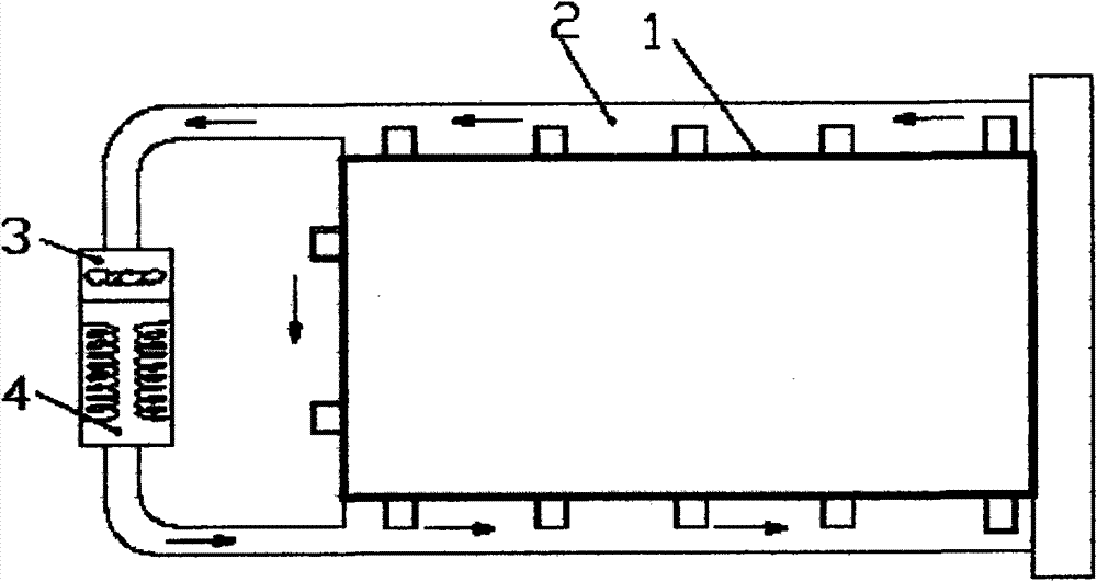
Because the thermal power source is composed of the fan 3 connected to the outer channel 2 and the constant temperature heating box 4 installed at one end of the fan 3 to form an external surrounding hot air circulation mode, when baking at a constant temperature for heating or heat dissipation, this hot air circulation mode It is easy to cause uneven heat transfer between the heat around the inner wall of the working box 1 and the heat in the center of the working box 1, so that the temperature around the inner wall is high, while the temperature in the center is low, resulting in an uneven temperature difference inside the working box 1
This method of heating the gas, then heating the outer wall of the working box with the heated gas, and then heating the gas in the working box by the outer wall, and then heating the object to be heated by the hot gas in the working box has a slow heating speed, unbalanced heating, and heat loss. big loss

Method used


Image

  • Novel energy-saving vacuum oven
  • Novel energy-saving vacuum oven
  • Novel energy-saving vacuum oven

Examples


Embodiment Construction

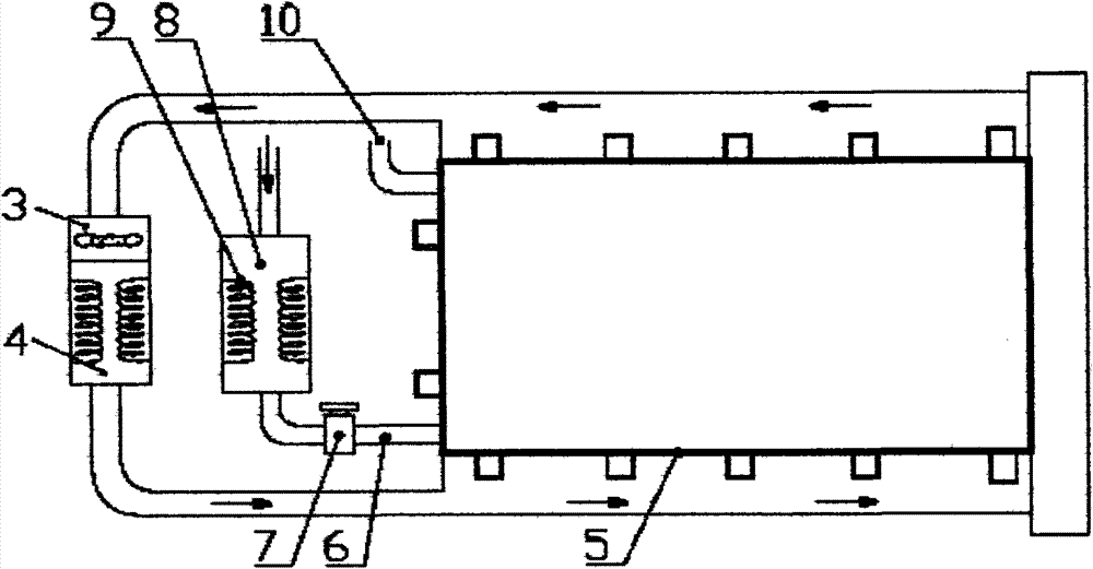
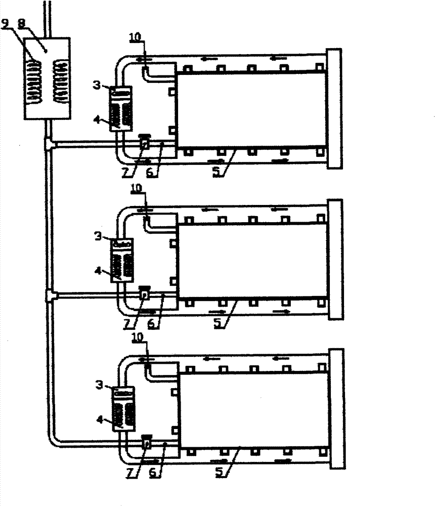
[0021] Please refer to figure 2 As shown, a specific implementation of the new energy-saving vacuum oven, its structure includes a working box 5 installed inside the main body of the oven, and one end outside the working box is provided with a constant temperature adjustment and equalization device. A peripheral hot air circulation channel is arranged on the periphery of the working box, and a thermal power source 3 and a heat source 4 are arranged in the peripheral hot air circulating channel. The constant temperature adjustment and balancing device includes a vacuum pipeline 6 connected with the working box A control valve 7 on the vacuum pipeline 6 for controlling the flow rate of the transfer medium, and a thermostatic regulating box installed on the vacuum pipeline 6 at the input end of the control valve 7 . The constant temperature adjustment and equalization device can be used for heating the transfer medium, and in addition, the constant temperature adjustment and equ...


PUM


Abstract

The invention relates to a novel energy-saving vacuum oven, which comprises a work box body and a peripheral hot air circulation device, wherein the work box body is arranged inside an oven body, the peripheral hot air circulation device is arranged outside the work box body and is used for supplementing heat for the heat radiation of the outer wall of the work box body, and a constant temperature regulation balance device is arranged on the work box body. When the novel energy-saving vacuum oven works, transmission media inside the novel energy-saving vacuum oven are heated through the constant temperature regulation box, so the transmission media are formed into heat transmission media. When the vacuum pumping of the work box body is completed, the heat transmission media are released in the work box body, so the temperature inside the work box body is fast raised to the set temperature, and at the same time, the peripheral hot air circulation supplements the heat for the heat radiation of the outer wall of the box body. The permeation heating mode has the advantages that the temperature rise of baked objects is faster, the temperature is more uniform, local high temperature cannot occur, the heat is directly transmitted to baked objects through the heating air, the heat transmission links are reduced, the loss of a large amount of heat can not be caused, because of too many heat transmission links, and the heat utilization rate is improved.

Description

【Technical field】 [0001] The invention relates to a baking device, in particular to a novel energy-saving vacuum oven used in the field of making lithium batteries. 【Background technique】 [0002] Please refer to figure 1 As shown, there are various vacuum ovens for baking lithium batteries in the prior art, and most of the vacuum ovens include an oven main body, a working box 1 installed inside the oven main body, and a working box 1 formed in the working box 1. The peripheral outer channel 2 and the thermal power source arranged on the outer channel 2 . Because the thermal power source is composed of the fan 3 connected to the outer channel 2 and the constant temperature heating box 4 installed at one end of the fan 3 to form an external surrounding hot air circulation mode, when baking at a constant temperature for heating or heat dissipation, this hot air circulation mode It is easy to cause uneven heat transfer between the heat around the inner wall of the working box...

Claims


Application Information

Patent Timeline
Patent Type & Authority Patents(China)
IPC IPC(8): H01M10/058
CPCY02E60/10Y02P70/50
Inventor 杨志明
Owner SHENZHEN XINYUREN TECH
Learn More