Eureka AIR delivers breakthrough ideas for toughest innovation challenges, trusted by R&D personnel around the world.

Vertical lifting container

A vertical lifting and container technology, applied in the directions of transportation, packaging, storage devices, etc., can solve problems such as the inability to quickly place or take out the goods, the transmission accuracy requirements cannot be met, and the efficiency of the goods transportation is affected, so as to avoid shaking and maintenance. Fast, simple effects

Active Publication Date: 2010-10-06
南京音飞储存设备(集团)股份有限公司
View PDF7 Cites 29 Cited by
  • Summary
  • Abstract
  • Description
  • Claims
  • Application Information

AI Technical Summary

Problems solved by technology

[0004] 1. The existing lifting platform for vertically lifting containers is lifted by chains installed at the four corners of the lifting platform. Since the chain is suspended in the air, the chain will be loose due to various reasons. In this way, the chain often shakes during the up and down process. This will cause the lifting platform to tilt, and the tilt of the platform will cause the danger of goods falling, affect the efficiency of goods delivery, and pose a safety hazard
[0005] 2. It is difficult to ensure the stability of the horizontal movement of the pallet in the process of extracting and retracting the pallet device of the existing vertical lifting container. The poor stability of the pallet will cause the goods to be unable to be placed or taken out quickly, which will affect the efficiency of cargo transportation
[0006] 3. The driving device of the existing vertical lifting container generally adopts chain transmission. Since the chain transmission requires a tensioning mechanism, the chain will loosen after a period of movement, resulting in the failure of the transmission accuracy requirements, thus affecting the use effect of the equipment

Method used


Image

  • Vertical lifting container
  • Vertical lifting container
  • Vertical lifting container

Examples


Embodiment Construction

[0023] The present invention will be further explained below in conjunction with the accompanying drawings.

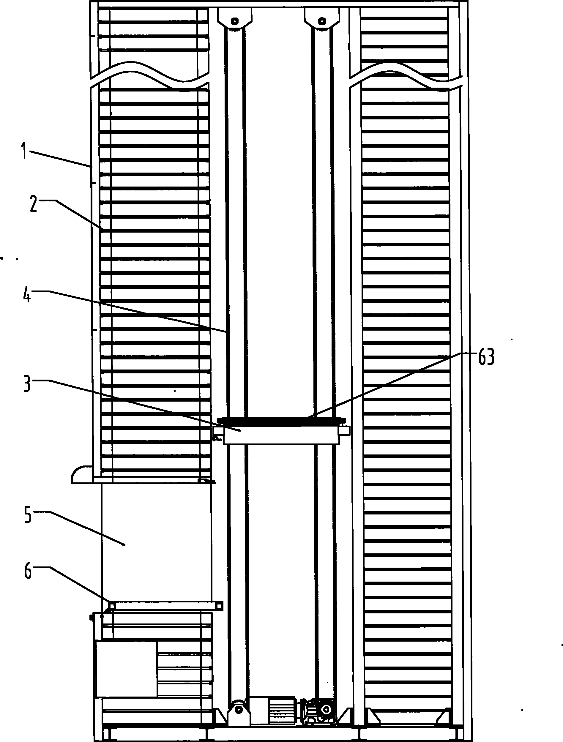
[0024] Such as figure 1 As shown, a vertical lifting container of the present invention comprises a cabinet body 1, and the two sides of the cabinet body are provided with corbels 2 for placing trays 6, and there is a lifting platform 3 running up and down between the corbels 2 on both sides of the cabinet body 1. In the channel, the lifting platform 3 is suspended in the channel by the lifting chain 4. One side of the cabinet body 1 is provided with a delivery port 5, and a pallet 6 for transporting goods in and out is arranged in the delivery port 5; the driving device drives the pallet 6 to move in translation.

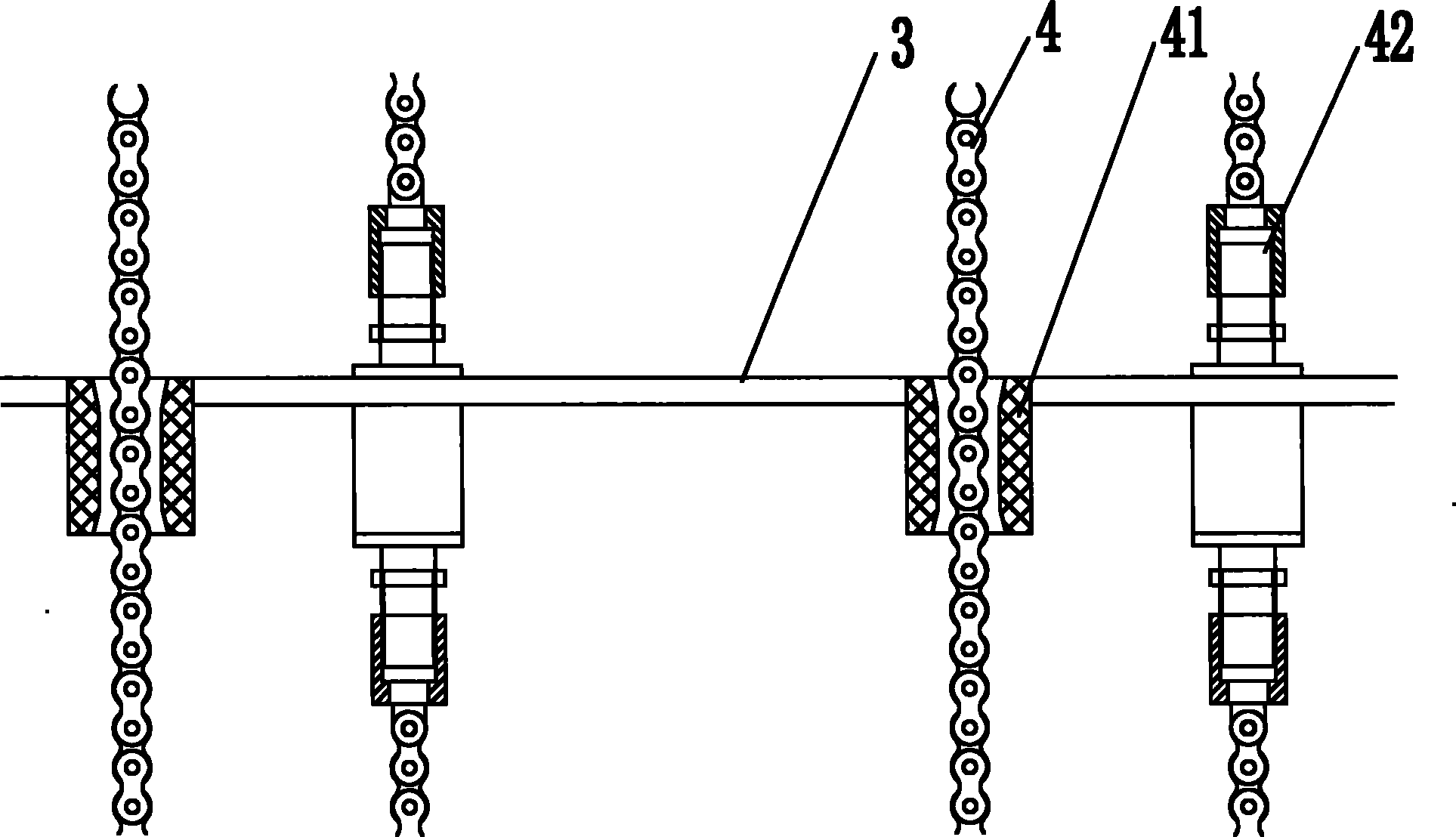
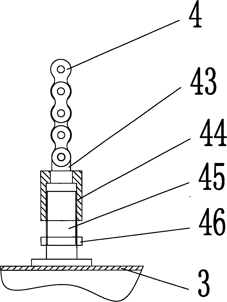
[0025] Such as figure 2 As shown, four corners of the lifting platform 3 are respectively provided with four chain suspension devices 41, the two ends of the lifting chain 4 are fixed by the chain suspension device 42, and the middle part of the chain sus...


PUM


Abstract

The invention discloses a vertical lifting container, which comprises a container body, a corbel for holding a pallet is respectively on the two sides of the container, a passage for the lifting platform to run from top to down is left between the cornels on the two sides of the container body, a lifting platform is hung in the passage through a lifting chain, one side of the container is provided with a goods outlet, the pallet for transporting into or out the goods is arranged in the goods outlet, and a drive device drives the pallet to translate. In the vertical lifting container of the invention, the pallet device is driven by a chain wheel device to smoothly and stably run, a guide device is arranged to further guarantee the smoothness of the pallet during the processes of drawing and withdrawing, so as to improve the operating efficiency of the goods and reduce running noise, and a chain tensioner can adjust the tension of the chain to avoid the swaying phenomenon and to enable the adjustment of the horizontal position of the lifting platform to be convenient. Since a guide upright similar to a guide rail is arranged, the vertical lifting platform can ensure the smoothness of the lifting platform and prevent the surface of the lifting platform from being oblique and shifted.

Description

technical field [0001] The invention relates to a storage device, in particular to a vertical lift container. Background technique [0002] The vertical lift cabinet is an automated storage device with pallets as storage units. The container lifting platform is a hoisting machine used for vertically transporting goods, and it is widely used in the field of storage equipment. Through the lifting movement of the platform traversing mechanism (lifting platform), the pallets storing the goods are taken out in front of the operator or sent to a suitable position in the cabinet. In the process of delivering the goods, the height of the stored items is detected through the automatic height measuring device at the entrance, so that the materials can be quickly stored in the best location in the warehouse, and the items can be picked up and delivered without manual handling. High-speed stocking can truly realize automatic storage. take process. [0003] But there are following pro...

Claims


Application Information

Patent Timeline
Patent Type & Authority Applications(China)
IPC IPC(8): B65G1/127
Inventor 金跃跃
Owner 南京音飞储存设备(集团)股份有限公司
Why Eureka
Eureka Blog
Learn More