Drive unit for ultrasonic probe and drive method thereof
A technology of ultrasonic probe and driving device, which is applied in the field of ultrasonic diagnostic instruments, can solve problems such as energy consumption, user experience, and heating of the driving device, and achieve the effects of solving severe heating, reducing power, and improving efficiency
- Summary
- Abstract
- Description
- Claims
- Application Information
AI Technical Summary
Problems solved by technology
Method used
Image
Examples
Embodiment 1
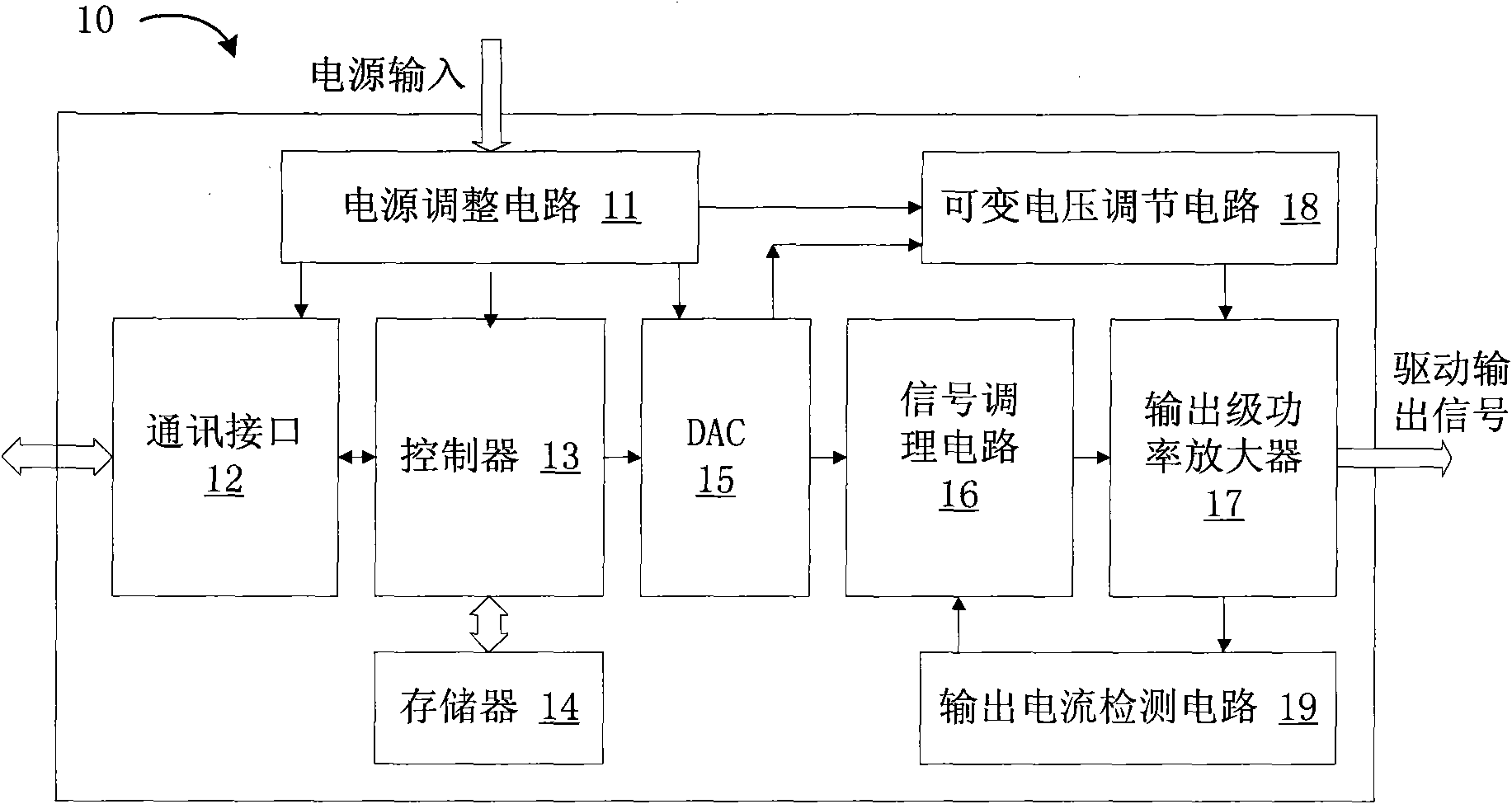
[0018] Please refer to figure 1 ,like figure 1 In one embodiment shown, the ultrasonic probe driving device 10 includes a power regulation circuit 11, a control unit, an output circuit 17 and a variable voltage regulation circuit 18, and each part will be described below.
[0019] Power supply adjustment circuit 11: provide energy input for each part of the entire driving device and the mechanical 3D ultrasonic probe. The power supply input can be DC voltage input, AC voltage input, or a combination of multiple AC and DC; power supply adjustment circuit 11 Adjust the power input to the voltage required by the other parts of the probe driver to operate properly, and power the various parts.
[0020] The control unit is configured to output a driving voltage command signal and a power supply voltage control signal according to user settings. In this embodiment, the control unit includes a controller, a digital-to-analog conversion circuit and a signal conditioning circuit.
...
Embodiment 2
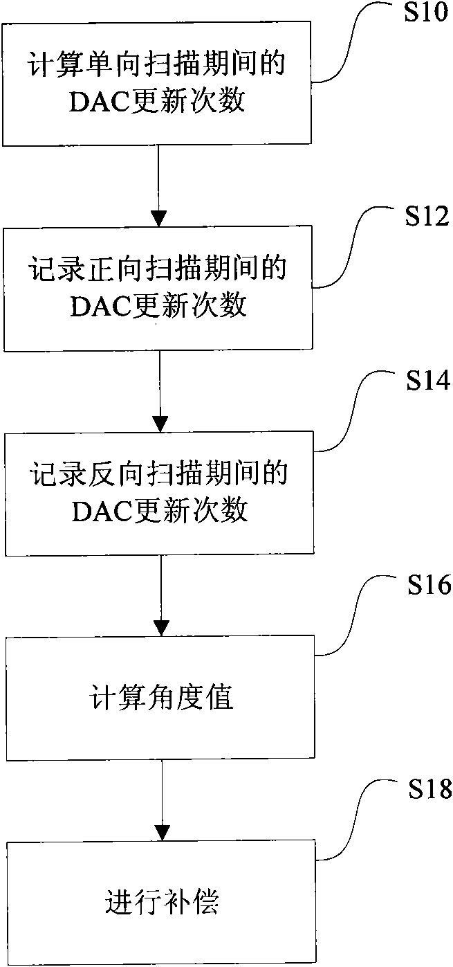
[0037] This embodiment is an improved solution based on the above embodiments. The controller 13 in the ultrasonic probe driving device 10 also performs reverse hysteresis compensation on the probe, and corrects the position information of the ultrasonic image obtained in at least one direction of the forward scanning and reverse scanning of the probe.
[0038] Mechanical 3D ultrasonic probes usually integrate a home position sensor inside the probe, which is usually a switch type position sensor; when the probe swings to a certain angle, the sensor will output a pulse signal or perform level reversal, and the probe drive device according to this signal to reset.
[0039] In addition, we know that the speed of the probe is proportional to the frequency of the driving voltage, the speed of the probe can be controlled by controlling the frequency of the driving voltage, and the angle of the probe swing is proportional to the phase of the driving voltage; in order to control the ...
Embodiment 3
[0050] This embodiment is a further improvement on the basis of the above embodiments. The controller in the ultrasonic probe driving device is also used to control the speed of the probe. The controller controls the number of updates and the update time of the digital-to-analog conversion circuit in one scanning direction. Interval sequence to control the probe swing angle and swing speed.
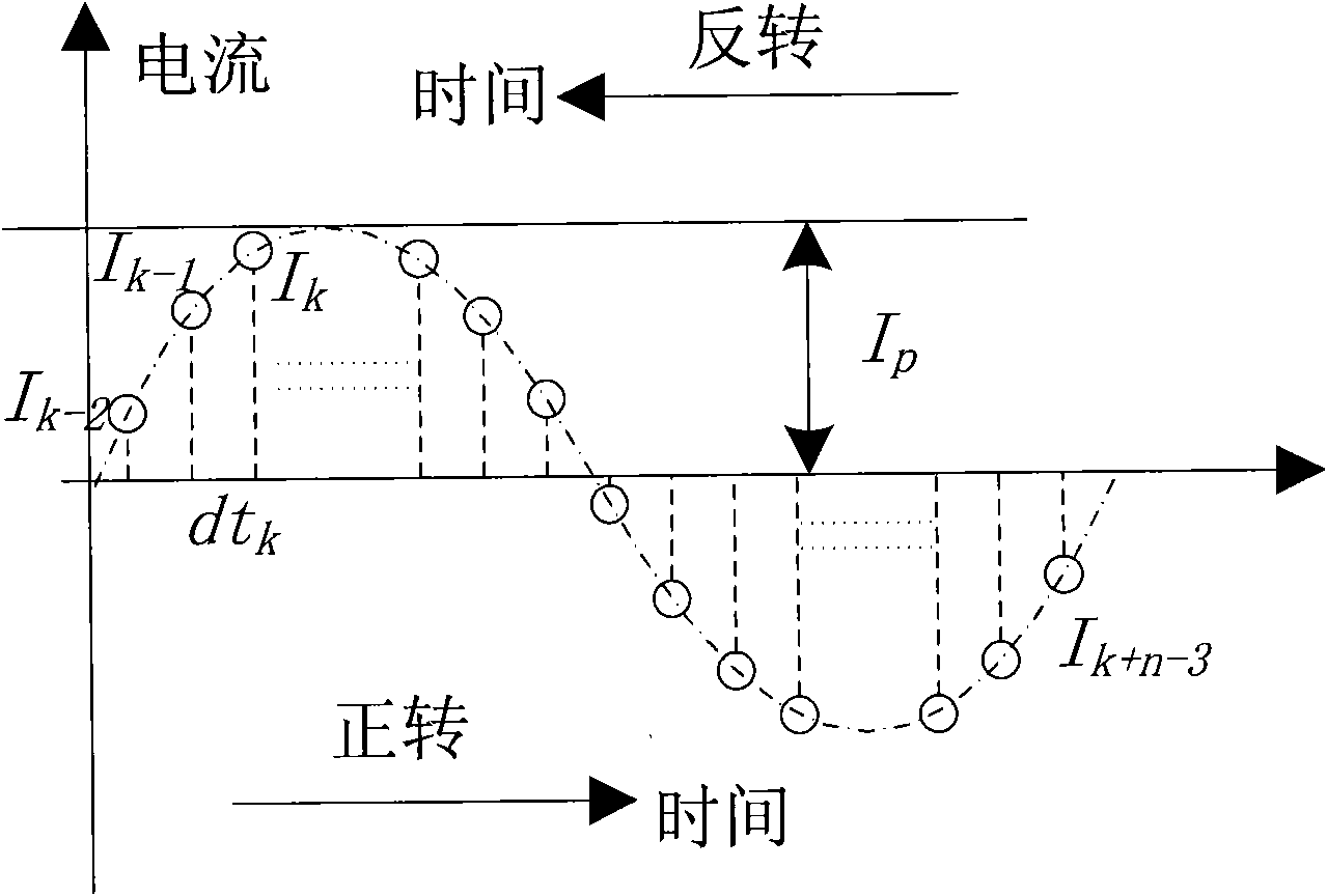
[0051] According to the second embodiment, a sine wave is divided into n parts at equal intervals to sample and output the current command signal. If the driving current waveform is cycled every cycle, and the angle of the probe swing is θ, then every interval, that is, every interval of the DAC One update means that the probe will swing by an angle of θ / n. In this way, controlling the time interval between two adjacent DAC data updates can control the frequency of the probe driving voltage, and then control the speed of the probe swing; controlling the number of DAC data updates can cont...
PUM
 Abstract
Description
Claims
Application Information
 - R&D
- Intellectual Property
- Life Sciences
- Materials
- Tech Scout
- Unparalleled Data Quality
- Higher Quality Content
- 60% Fewer Hallucinations
Browse by: Latest US Patents, China's latest patents, Technical Efficacy Thesaurus, Application Domain, Technology Topic, Popular Technical Reports.
© 2025 PatSnap. All rights reserved.Legal|Privacy policy|Modern Slavery Act Transparency Statement|Sitemap|About US| Contact US: help@patsnap.com


