Method for preventing surfaces of disc cams from generating gear marks

A disc-shaped cam and tool mark pick-up technology, which is used in grinding machine parts, automatic grinding control devices, metal processing equipment, etc. Improve the textile speed, the error is easier to control, and the effect of eliminating knife marks

Inactive Publication Date: 2010-09-29
CHANGZHOU INST OF TECH
View PDF4 Cites 8 Cited by
  • Summary
  • Abstract
  • Description
  • Claims
  • Application Information

AI Technical Summary

Problems solved by technology

In his doctoral dissertation of Huazhong University of Science and Technology "Key Technology of Camshaft High-speed Grinding Control System" (2008), Gong Shihua mentioned that the discrete points should be fitted with curves first, and then the spline curve equations of the discrete points should be obtained; Find the contour curve equation of the entire cam within the error range. Since the curve is smooth, it can indeed eliminate the tool mark; however, because the disc cam contour is complex, the curve fitting cannot fit the entire contour, so it is necessary to fit it in sections , and the length of the segment will directly affect the error between the fitted data and the original data; however, the selection of the segment length is often difficult, and there is no definite selection criterion. Curves are not smooth at the junctions between segments
Therefore, the operability of the curve fitting method is more difficult, and the error is more difficult to control, resulting in the poor generality of the method

Method used


Image

  • Method for preventing surfaces of disc cams from generating gear marks
  • Method for preventing surfaces of disc cams from generating gear marks

Examples


Embodiment 1

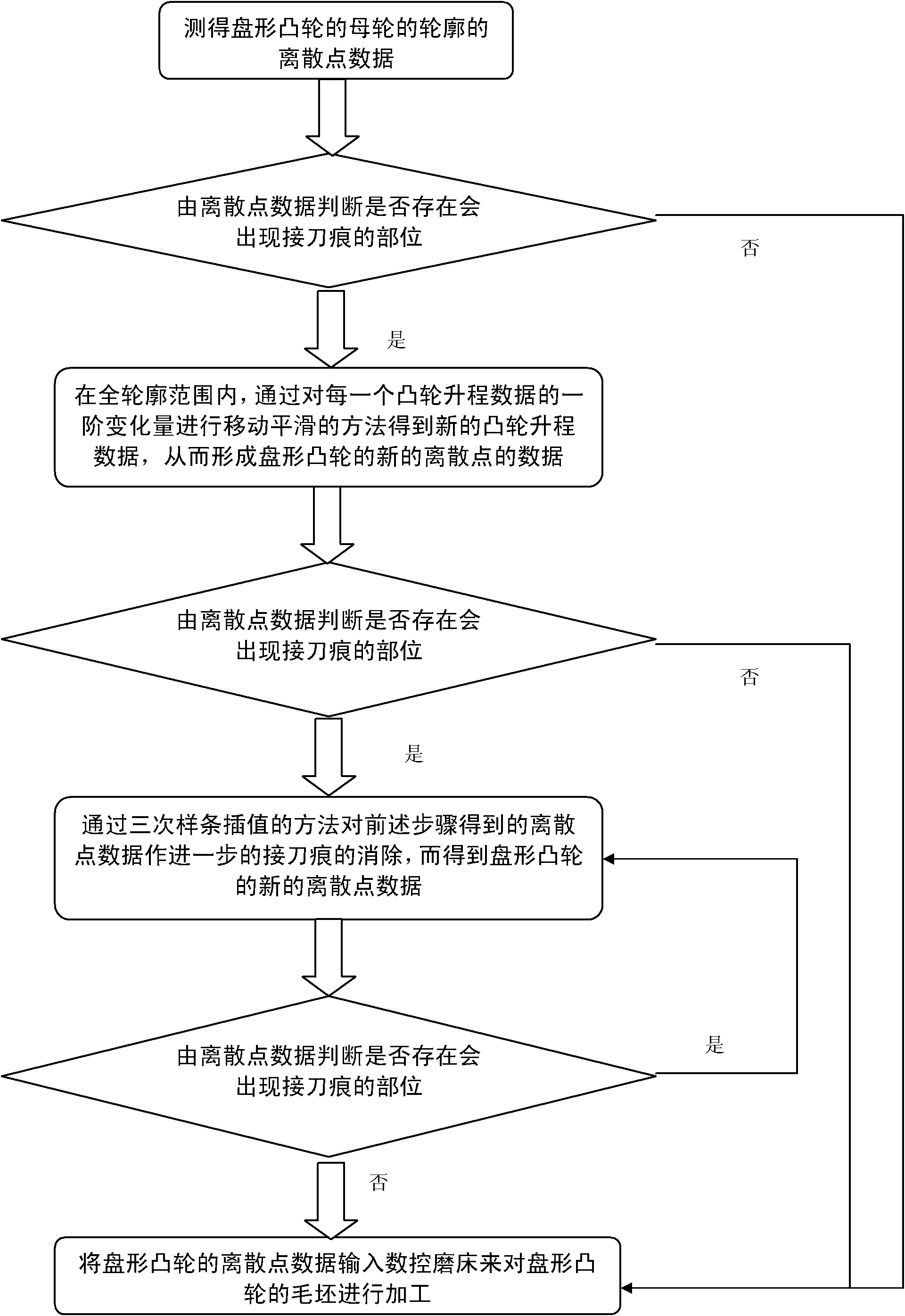
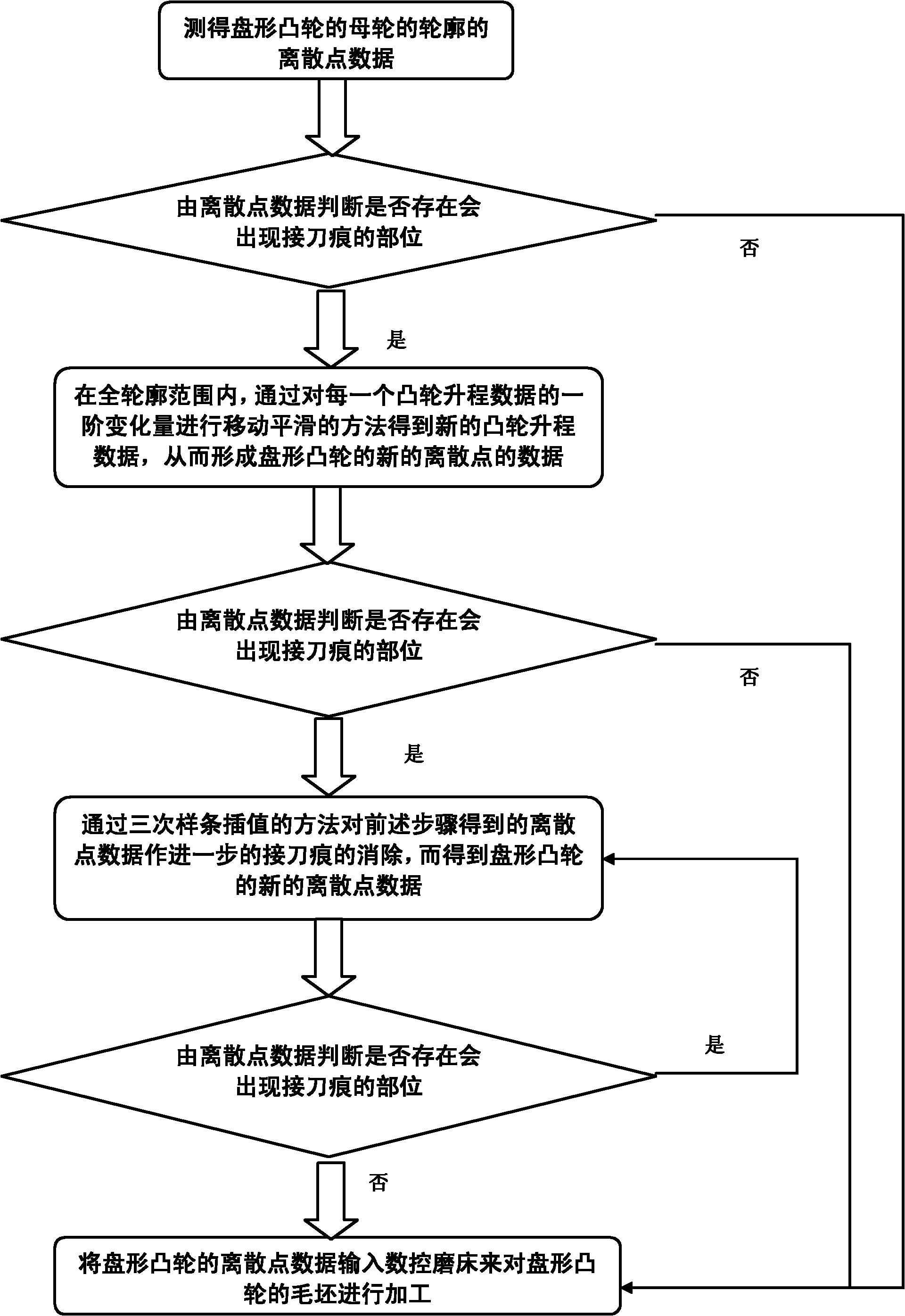
[0029] See figure 1 , the method for avoiding the surface of the disc cam to produce the knife mark of the present embodiment comprises the following steps:

[0030] ① The discrete point data of the profile of the disc cam’s parent wheel is measured by the cam precision measuring instrument, and the cam rotation angle signal is obtained by the circular grating encoder of the cam precision measuring instrument, which is obtained by the measuring head and linear grating of the cam precision measuring instrument The displacement signal of the cam lift, and then input the discrete point data of the profile of the measured cam into the computer through the data acquisition card, and in the form of polar coordinates {ρ m , θ m}, where m=1, 2, 3, Λ, k (k=360 / (θ 2 -θ 1 )), ρ m is the mth cam lift data, θ m is the mth sampling angle value, and θ 2 is the second sampling angle value, θ 1 is the first sampling angle value; by (ρ m , θ m ) represents the data of any sampling poin...

Embodiment 2

[0052] In this embodiment, the cam of a certain type is sampled at the angle (ie θ m ) 20 lift data measured from 301 degrees to 320 degrees are processed by the method of embodiment 1 to prevent the cam surface from generating tool marks.

[0053] By step 1. of the method for embodiment 1, measure the discrete point data of the profile of disc cam by cam precision measuring instrument, the lift data of the cam that measures is as shown in table 1 (unit is millimeter), here only selects A section of the area where more knife marks appear. Each sample value is separated by an angle of 1 degree.

[0054] From step ② of the method in Example 1, it can be seen that among these sampling points, the sampling points whose absolute value of the second-order variation is greater than 0.03 are the parts where the knife marks will be generated. From the second-order variation in the fourth column in Table 1 It can be found that 305 degrees, 307 degrees, 310 degrees, 312 degrees, 314 de...

Embodiment 3

[0059] According to step 5. of the method of embodiment 1, by the method for cubic spline interpolation, the data obtained by step 4. of embodiment 2 insert a point at the midpoint of adjacent 2 discrete points and carry out cubic spline interpolation, obtain The data are shown in Table 2 below. It can be seen from Table 2 that the absolute value of the second-order variation of the cam data after cubic spline interpolation does not exceed 0.008, and when the interval angle from the sampling angle is 0.5 degrees, the threshold of the second-order variation of the tool mark will be 0.015 The difference is far, so there is no place where the knife mark will be produced.

[0060] Sampling angle value


PUM


Abstract

The invention discloses a method for preventing the surfaces of disc cams from generating gear marks, comprising the following steps of: after measuring the discrete point data [pmrho m, theta m] (wherein rho pm is the mth cam lift data, and theta m is the mth sampling angle value) of the profiles of mother wheels of the disc cams by utilizing a cam precise measurer, judging whether positions capable of generating the gear marks exist or not by using the discrete point data of the profiles of the cams, if the positions capable of generating the gear marks exist, reducing the second-order variation of the lift data by carrying out a smooth moving method on the first-order variation of the lift data of each cam to eliminate the gear marks; and if the positions capable of generating the gear marks still exist in the discrete point data through the operation, carrying out further gear mark elimination on the data obtained in the last step through a multi-time cubic spline interpolation method until the second-order variation of the lift data achieves meets the requirements of thresholds, and then inputting the new discrete point data to a numerically controlled grinder for processing the cam. By adopting the method, the disc cams with smooth and precise profiles can be obtained.

Description

technical field [0001] The invention relates to a method for avoiding tool marks on the surface of a disc-shaped cam during the process of processing the cam with a numerically controlled cam grinder. Background technique [0002] Disc cams or camshaft parts play an important role in mechanical equipment in many fields, such as in the automotive industry and textile machinery industry, especially fine knitting machines in high-end textile machinery. Conjugate cams are the most critical parts. It needs to have enough precision to ensure the strictness of the process and fine craftsmanship in the weaving process, and finally ensure the high quality of the weaving products. Disc cams or camshafts require high grinding precision and productivity due to their complex surface contours. How to improve the grinding efficiency and processing quality is an urgent problem to be solved in the control of cam grinding process. [0003] In recent years, the combination of numerical contr...

Claims


Application Information

Patent Timeline
Patent Type & Authority Applications(China)
IPC IPC(8): B24B19/12B24B51/00
Inventor 毛国勇张建生黄文生徐磊范力旻
Owner CHANGZHOU INST OF TECH
Why Eureka
Try Eureka