Squeeze mop

A squeezing and mopping technology, used in carpet cleaning, floor cleaning, cleaning equipment, etc., can solve problems such as poor cleaning results and unfavorable use characteristics

Inactive Publication Date: 2010-09-15
CARL FREUDENBERG KG
View PDF1 Cites 3 Cited by
  • Summary
  • Abstract
  • Description
  • Claims
  • Application Information

AI Technical Summary

Problems solved by technology

In the case of such cleaning appliances, even small changes in the angular position of the handle relative to the surface to be cleaned produce unfavorable use characteristics and poor cleaning results

Method used


Image

  • Squeeze mop
  • Squeeze mop
  • Squeeze mop

Examples


Embodiment Construction

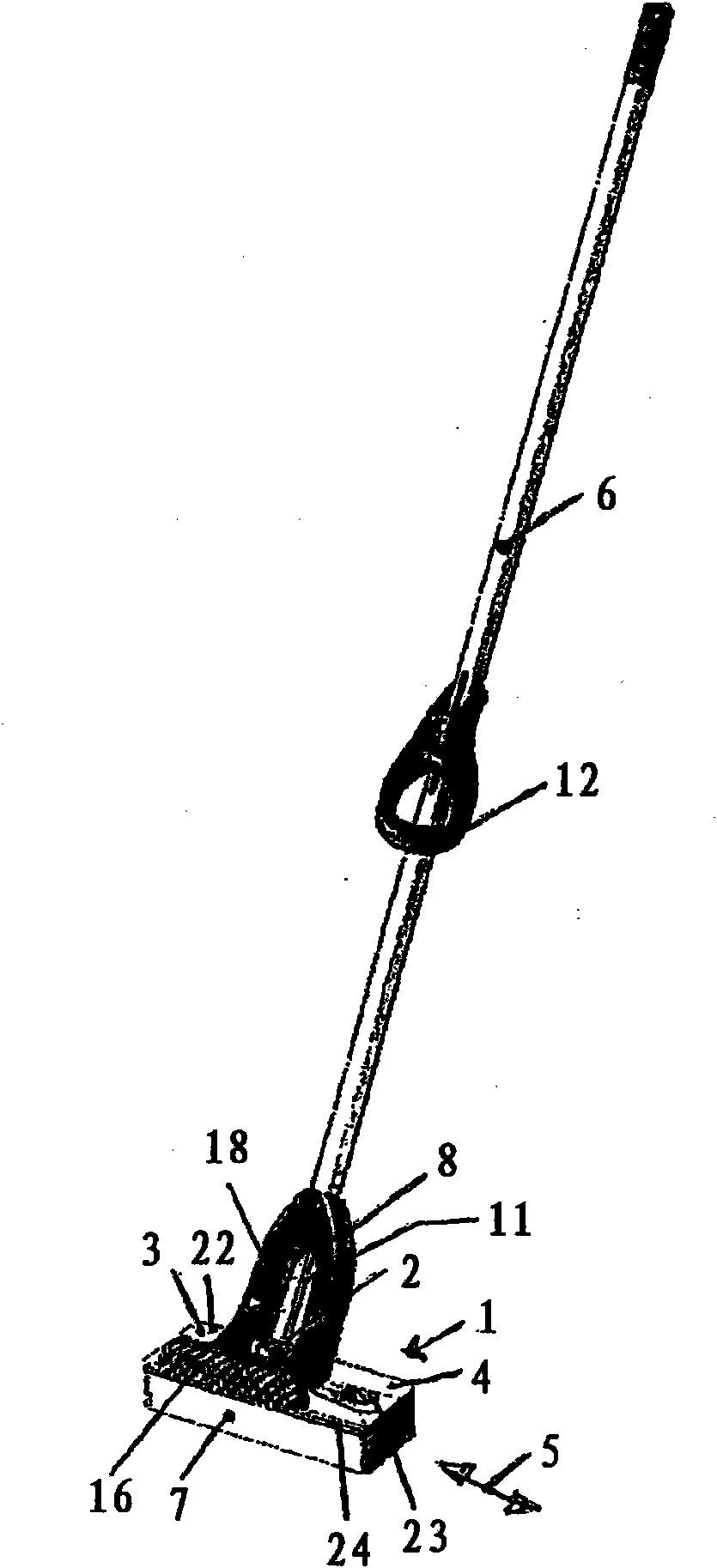
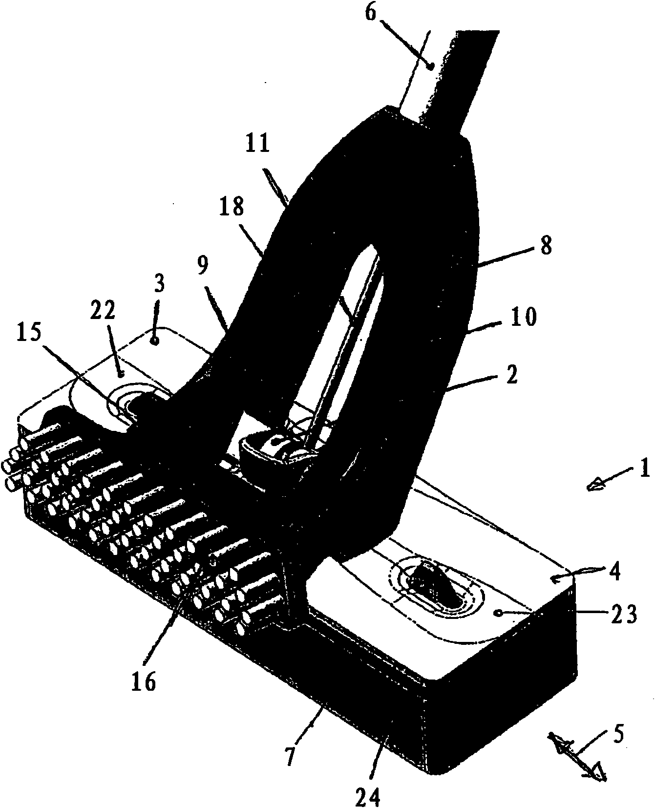
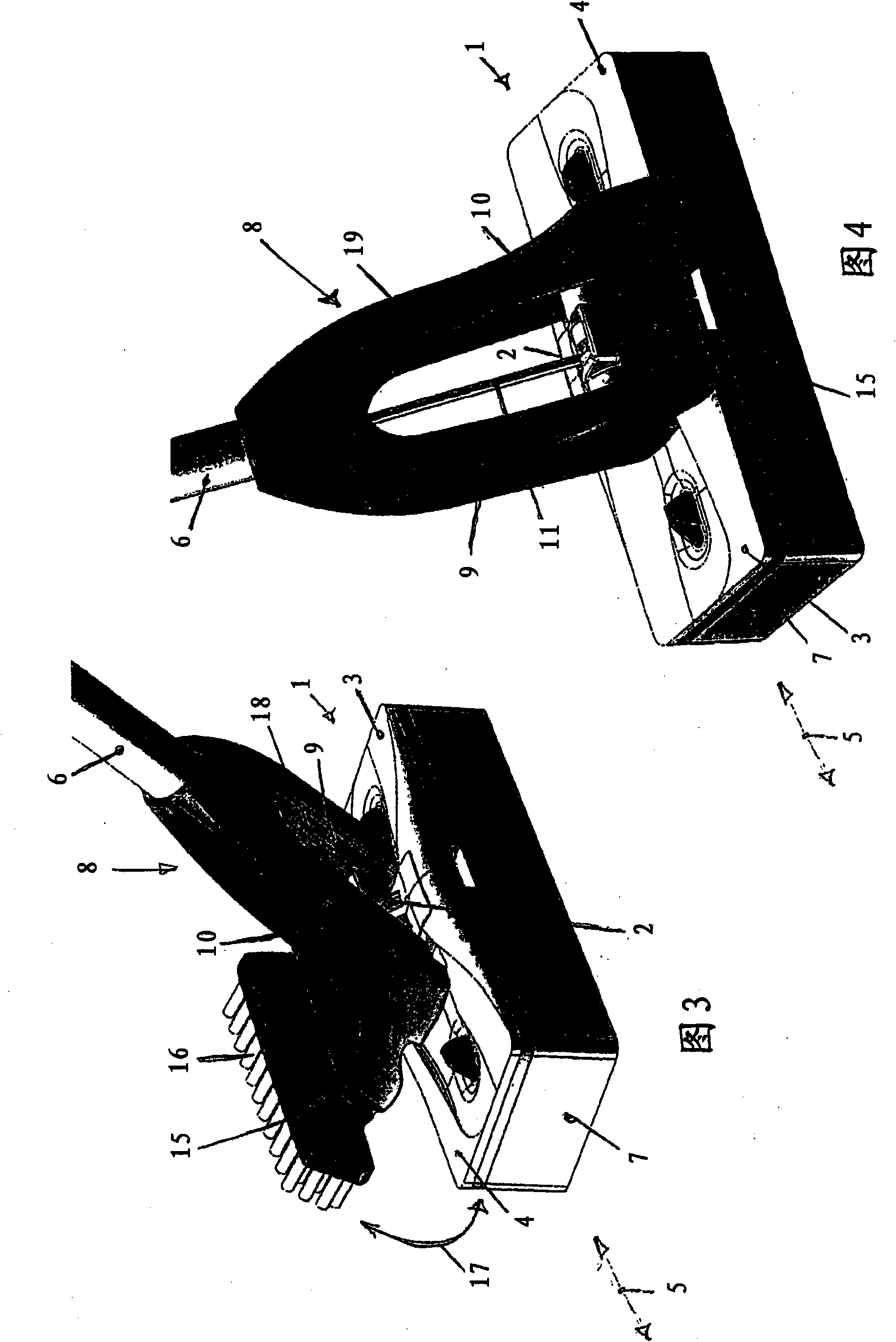
[0030] exist figure 1 and in Figure 2 to Figure 13 An exemplary embodiment of a squeeze mop according to the present invention is shown in . The squeeze mop comprises a carrier body 1 made of a polymer material and comprising a centrally arranged double joint 2, wherein in the longitudinal direction 5 of the carrier body 1 Corresponding wings 3 , 4 follow on both sides. The double joint 2 and the two wings 3 , 4 are connected to each other such that when the squeezing device 8 is actuated, the two wings 3 , 4 can each be swung downwards relative to the double joint 2 . On the side facing away from the handle 6 in the axial direction, the carrier body 1 has a single-part mop pad 7 which corresponds to the dimensions of the carrier body 1 and is designed in the form of a sponge. Instead of the single-part mop pad 7 described here, it is possible to use a multi-part mop pad, such as a two-part mop pad, in which case each part has the same dimensions as, for example, a wing p...


PUM


Abstract

A squeeze mop, comprising a carrier body (1) that is formed by a double joint (2) and two wing plates (3, 4) that are arranged in the longitudinal direction (5) of the carrier body (1) on both sides of the double joint (2) and are connected to the double joint. The invention further comprises a handle (6), wherein the carrier body (1) on the side facing axially away from the handle (6) comprises a cleaning pad (7) that substantially corresponds to the size of the carrier body (1), and wherein the wing plates (3, 4) can be pressed against each other by means of a squeeze device (8), wherein the squeeze device (8) is designed in a fork shape and is open on the side facing axially away from the handle (6). The squeeze device comprises two pressure arms (9, 10) that are arranged substantiallyparallel to each other and can be engaged with the wing plates (3, 4) for folding the wing plates (3, 4) around the double joint (2). The squeeze device (8) is connected to the handle (6). The handle(6) is connected to the double joint (2) at least pivotally about the longitudinal axis (5) of the carrier body (1), wherein the squeeze device (8) comprises an actuating rod (11) that is moveable inthe axial direction of the handle (6) and that is connected both to the double joint (2) and to a pivotable hand grip (12) that is fixed in a stationary manner on the handle (6) for actuating the squeeze device (8).

Description

technical field [0001] The invention relates to a squeeze mop comprising a carrier formed by a double joint and two wings arranged on both sides of the double joint in the longitudinal direction of the carrier and connected to the rear and the mop also includes a handle, wherein the carrier has a mop pad substantially corresponding to the size of the carrier on the side of the carrier axially directed away from the handle, and wherein the wings can be pushed through a squeeze The net device presses against each other, wherein the squeeze device is designed in a bifurcated form and is open on the side directed away from the handle in the axial direction, and it comprises two arms applying pressure, which are basically are arranged parallel to each other and can come into engagement with the flaps so that the flaps are folded around the double joint to which the squeezing device is connected, and wherein the handle is connected to the double joint so that It is pivotable at lea...

Claims


Application Information

Patent Timeline
IPC IPC(8): A47L13/12A47L13/146
CPCA47L13/12A47L13/146
Inventor N·韦斯
Owner CARL FREUDENBERG KG
Why Eureka
Try Eureka