Eureka AIR delivers breakthrough ideas for toughest innovation challenges, trusted by R&D personnel around the world.

Seal and corresponding sealing assembly

A technology of seals and seals, which is applied in the direction of engine seals, charging systems, passing components, etc., and can solve problems such as damage and destruction of elastic materials

Active Publication Date: 2013-02-13
CARL FREUDENBERG KG
View PDF8 Cites 4 Cited by
  • Summary
  • Abstract
  • Description
  • Claims
  • Application Information

AI Technical Summary

Problems solved by technology

For applications where the seal is placed between 200°C and 300°C, seals made of elastomeric materials are not suitable as the elastomeric material can be damaged / destroyed during use at these high temperatures

Method used


Image

  • Seal and corresponding sealing assembly
  • Seal and corresponding sealing assembly
  • Seal and corresponding sealing assembly

Examples


Embodiment Construction

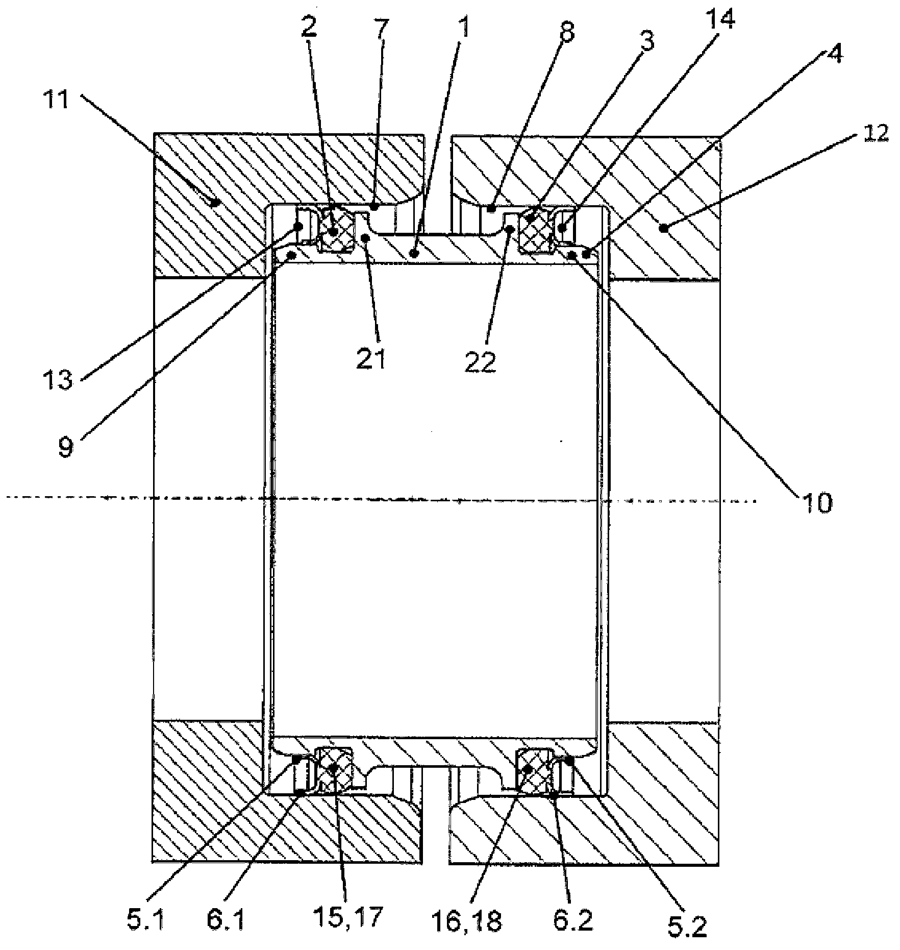
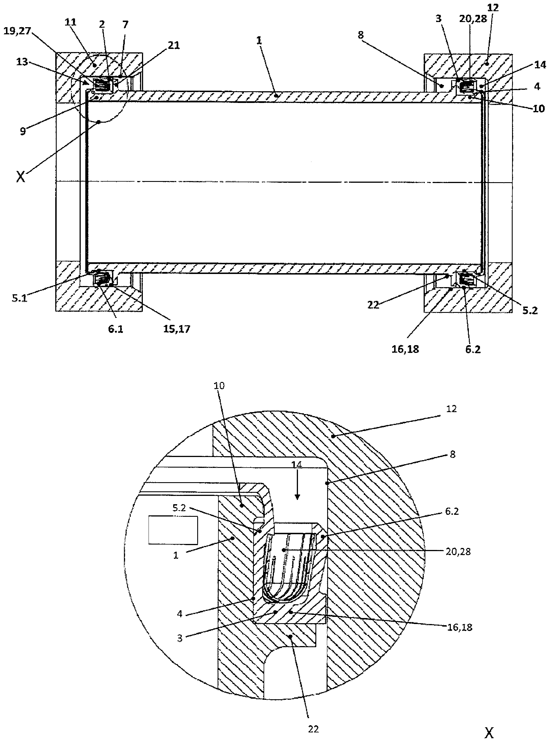
[0032] in Figure 1 to 4 Examples of seals are shown in respectively, where these seals are components of a sealing device.

[0033] In each of the embodiments shown here, the seal includes a tubular carrier 1 made of metal material. The carrier 1 has a groove-shaped groove that opens outward in the radial direction on the outer peripheral side in the region of its two end portions 9, 10, respectively, and an annular sealing body 2 is respectively placed in the groove. 3. The sealing bodies 2 and 3 each hermetically surround the carrier 1.

[0034] The sealing device shown here is used in the charge air system of a truck or car. In order to adapt to this application, the materials used are required to be high temperature resistant. "High temperature resistance" means that the materials used can withstand temperatures up to at least 300°C. For this reason, the use of elastic materials as the annular sealing bodies 2, 3 is excluded.

[0035] In the embodiment shown here, the sealin...


PUM


Abstract

A seal including a tubular carrier body (1) and two annular sealing elements (2, 3), wherein the carrier body (1) on both sides of its front face is respectively enclosed by one of the sealing elements (2, 3) on the side of its outer perimeter forming a seal. At least one of the sealing elements (2, 3) is made of a non-elastomeric high-temperature resistant sealing material.

Description

Technical field [0001] The invention relates to a sealing element, which comprises a tubular carrier and two annular sealing bodies, wherein the two ends of the carrier are respectively enclosed by a sealing body on the outer periphery side. Background technique [0002] Seals of this type are well known and are for example constructed as inserts for sealing two housings or pipe joints from a medium such as gas or liquid under pressure and temperature. The sealing body of the known seal is made of an elastic material. For applications where the seal is placed between 200°C and 300°C, the sealing body made of elastic material is not suitable because the elastic material will be damaged / damaged under the above-mentioned high temperature during use. Summary of the invention [0003] The task of the present invention is to further improve the known type of seal so that it can reliably achieve sealing in a temperature range of 200°C to 300°C during a long period of use. [0004] Accord...

Claims


Application Information

Patent Timeline
IPC IPC(8): F16J15/10F16J15/12
CPCF02M35/10157F02M35/10321F02M35/10144F02B33/44Y02T10/144F16L27/1017F16L21/035F16J15/028F16J15/061F16L21/022F16L27/113Y02T10/12
Inventor 托马斯·耶克汉斯·翁格尔拉尔夫·海尔德曼莱纳·蒂尔
Owner CARL FREUDENBERG KG
Why Eureka
Eureka Blog
Learn More