
Crimping terminal of collector belt

A terminal and card cover technology, which is applied in the direction of connection, contact parts, clamping/spring connection, etc., can solve the problems of large size, trouble, and tools for connecting the bus belt, and achieve reliable wiring, safe work, and compact structure. Effect

Inactive Publication Date: 2010-09-15
镇江贝德科技有限公司 +1
View PDF5 Cites 6 Cited by
  • Summary
  • Abstract
  • Description
  • Claims
  • Application Information

AI Technical Summary

Problems solved by technology

The obvious disadvantage reflected in its use is that tools are needed to assemble the confluence belt, which is troublesome
In addition, a large space is required in the cavity of the card cover during assembly, so the overall volume is relatively large

Method used


Image

  • Crimping terminal of collector belt
  • Crimping terminal of collector belt
  • Crimping terminal of collector belt

Examples


Embodiment 1

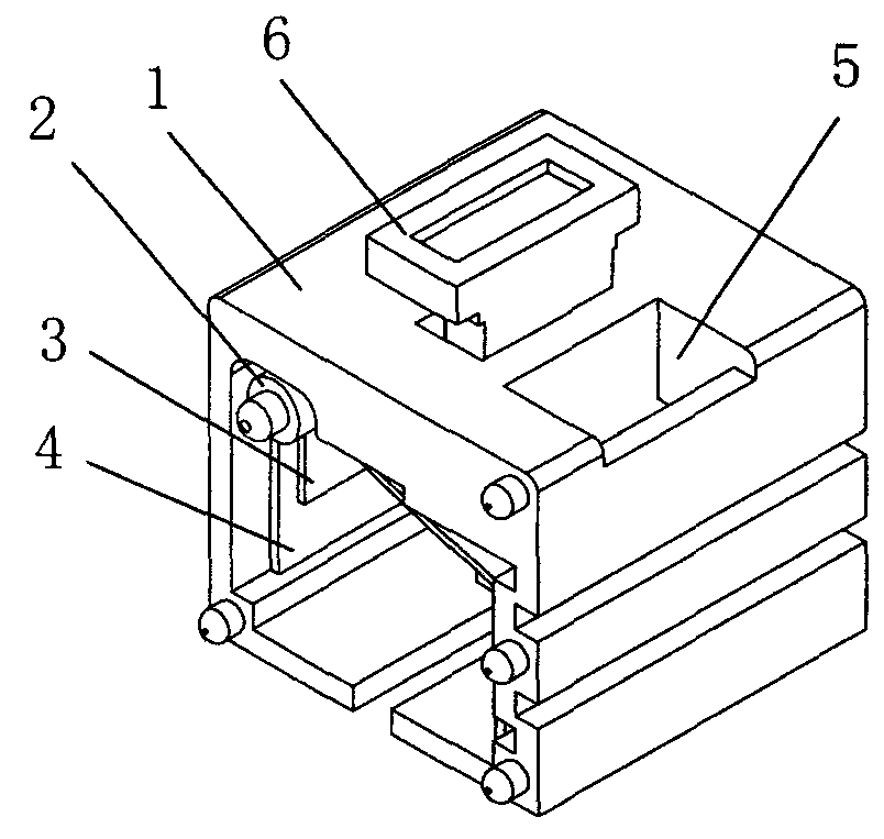
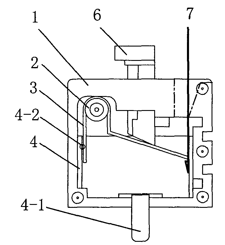
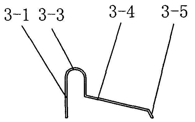
[0017] The busbar crimping terminal of this embodiment is as figure 1 , figure 2 As shown, a cavity is formed inside the insulating card cover 1 with an opening on one side, and the terminal body is formed after the end cover covers the opening. The conductive card holder 4 and the clamp spring 3 are arranged in the insulating card cover 1 . Conductive deck 4 such as Figures 6 to 8 As shown, the conductive metal is bent into a "gate" shape, with a first surface 4-3, a second surface 4-4 opposite to the first surface, and a connecting surface 4-5 connecting the first surface and the second surface . Positioning bumps 4-2 are formed on the first surface 4-3. When installed, the conductive card base 4 is clamped on the inner wall of the insulating card cover 1, and extends from the bottom of the insulating card cover 1 to an extended end 4-1 for connecting with the printed board. Circlip 3 such as Figures 3 to 5 As shown, it is composed of a vertical surface 3-1 and an i...


PUM


Abstract

The invention relates to a crimping terminal of a collector belt, belonging to the technical field of electric power transmission facility. An electrically conductive deck and an electrically conductive clamp spring are arranged in an insulation clamp hood; the electrically conductive deck is lined at the inner wall of the insulation clamp hood and has an extended end stretch out from the bottom of the insulation clamp hood; the clamp spring is composed of a vertical plane and an inclined folding plane which are in transitional connection by an arc bend; the vertical plane is close to the first side of the inner wall of the insulation clamp hood and is in fit positioning with the first plane of the electrically conductive deck; the arc bend is erected in the insulation clamp hood by a limit hinged shaft; the inclined folding plane stretches towards the second side corresponding to the first side of the insulation clamp hood and is inclined to pressed against the second plane of the electrically conductive deck; and a press-button with the lower end thereof pressed against the inclined holding plane is inserted at the upper end of the insulation clamp hood, one end of the press-button is provided with collector belt through holes which have access to the second plane of the electrically conductive deck. The installation of the invention is very convenient in that no auxiliary tools are needed. The invention also features compact structure and can execute self-locking, thus ensuring reliable wiring and safe operation.

Description

technical field [0001] The invention relates to a connection terminal, in particular to a busbar crimping terminal, which belongs to the technical field of electric power transmission facilities. Background technique [0002] According to the applicant's knowledge, the existing busbar crimping terminal is mainly composed of an insulating clip cover, a busbar retaining spring and a connecting base. The obvious disadvantage reflected in its use is that tools are needed to assemble the confluence belt, which is troublesome. In addition, a relatively large space is required in the housing cavity during assembly, so the overall volume is relatively large. Contents of the invention [0003] The purpose of the present invention is to provide a crimping terminal for a bus strip that is convenient to plug in and has a compact structure in view of the above-mentioned shortcomings in the prior art. [0004] In order to achieve the above purpose, the bus belt crimping terminal of th...

Claims


Application Information

Patent Timeline
Patent Type & Authority Applications(China)
IPC IPC(8): H01R12/28H01R4/48H01R13/629H01R13/02H01R12/79
Inventor 袁红彬
Owner 镇江贝德科技有限公司
Learn More