
Touch display and method for determining positions of touch points

A touch display and touch point technology, which is applied in the direction of instruments, calculations, electrical digital data processing, etc., can solve the problems of increasing the complexity of the internal structure of the display screen, increasing the difficulty of the production process of the display screen, and the refraction effect. The effect of steps and difficulty, simple structure and low cost

Inactive Publication Date: 2010-09-15
K TRONICS (SUZHOU) TECH CO LTD +1
View PDF0 Cites 0 Cited by
  • Summary
  • Abstract
  • Description
  • Claims
  • Application Information

AI Technical Summary

Problems solved by technology

[0003] The external touch display is made by superimposing the display screen for display and the touch screen for sensing the coordinates of the touch point, which not only makes the touch display relatively thick, but also makes the refraction effect easily exist due to the thickness of the touch screen superimposed on the upper layer. What you touch is not what you get, and there are also defects such as brightness drop or blurred display
The built-in touch display is to add sensing elements to the pixel area inside the display to realize the perception of the coordinates of the touch point. Although it solves the defects of the external touch display such as thickness and brightness reduction to a certain extent, it increases the internal structure of the display. The complexity, on the one hand, increases the difficulty of the production process of the display screen, and on the other hand, reduces the yield

Method used


Image

  • Touch display and method for determining positions of touch points
  • Touch display and method for determining positions of touch points
  • Touch display and method for determining positions of touch points

Examples


Embodiment Construction

[0046] The technical solutions of the present invention will be further described in detail below through the accompanying drawings and embodiments.

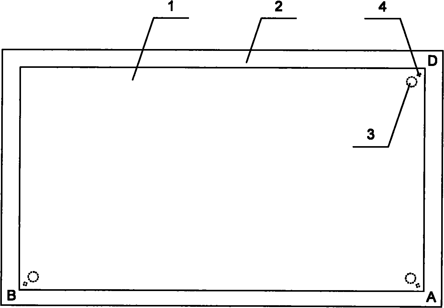
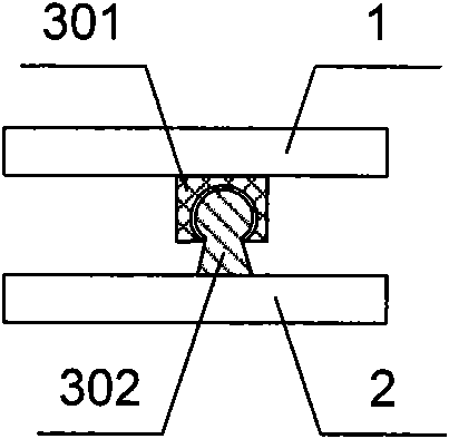
[0047] figure 1 Is a schematic structural diagram of the first embodiment of the touch display of the present invention, figure 2 for figure 1 Side view. Such as figure 1 with figure 2 As shown, the main structure of the touch display of this embodiment includes a display screen 1, a backlight source 2, three resistive angle sensors, and a data processing device (the data processing device is not shown). The display screen 1 is used for displaying images, and the backlight source 2. Used to provide a light source, three resistive angle sensors are arranged between the display screen 1 and the backlight source 2 which are parallel to each other and separated by a set distance. The same as the current change according to the deflection of the touched display screen 1, the data The processing device is connected to the three resisti...


PUM


Abstract

The invention relates to a touch display and a method for determining positions of touch points. The touch display comprises a fixed body and a deflector, wherein at least three resistance-type angular transducers are arranged between the fixed body and the deflector and generate current variations along with the deflection generated by the touched deflector; the resistance-type angular transducers are connected with a data processing device; the data processing device is used for acquiring position coordinates of the touch points according to the current variations of the resistance-type angular transducers; the fixed body is a backlight source; and the deflector is a display screen. By organically combining material mechanics with principles of electricity, compared with the built-in or external touch displays, the touch display of the invention has the advantages of simple structure, convenient installation, low manufacturing cost and the like, and has wide application prospects.

Description

Technical field [0001] The invention relates to a flat panel display, in particular to a touch display and a method for determining the position of a touch point. Background technique [0002] Currently, there are many types of touch displays in the prior art. According to the working principle, it mainly includes three types: inductive, capacitive and resistive. According to the structure, it mainly includes two types: external type and built-in type. But whether it is external or internal, its working principle is still limited to three types: inductive, capacitive and resistive. The resistive type is controlled by pressure sensing. By setting two conductive layers, the two conductive layers touch at the touch point position when the finger is touched, the resistance changes, and the touch point position is obtained from the resistance change. The capacitive type uses the current induction of the human body by setting a conductive layer and leads four electrodes on the four c...

Claims


Application Information

Patent Timeline
Patent Type & Authority Applications(China)
IPC IPC(8): G06F3/041
Inventor 周伟峰郭建明星
Owner K TRONICS (SUZHOU) TECH CO LTD
Learn More