
Piston positioning and locking device

A positioning and locking piston technology, applied in the field of metal cutting, can solve the problems of affecting the machining accuracy of the piston, increasing the manufacturing cost of the piston, and inconvenient operation, etc., and achieves the effect of simple structure, low cost, and convenient clamping and positioning

Inactive Publication Date: 2010-09-15
CSSC MARINE POWER
View PDF5 Cites 0 Cited by
  • Summary
  • Abstract
  • Description
  • Claims
  • Application Information

AI Technical Summary

Problems solved by technology

Due to the poor rigidity of the thin-walled cylinder at the lower part of the piston, clamping the outer circle of the lower part of the piston will cause its plastic deformation, and the piston needs to be aligned, which is inconvenient to operate and affects the machining accuracy of the piston, which will lead to serious consequences of scrapping the piston. Piston manufacturing cost

Method used


Image

  • Piston positioning and locking device
  • Piston positioning and locking device
  • Piston positioning and locking device

Examples


Embodiment Construction

[0017] The present invention will be further described below in conjunction with drawings and embodiments.

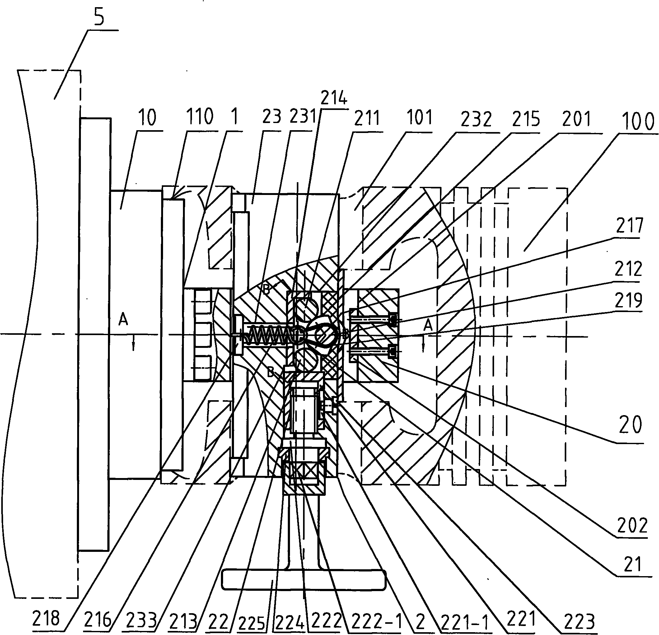
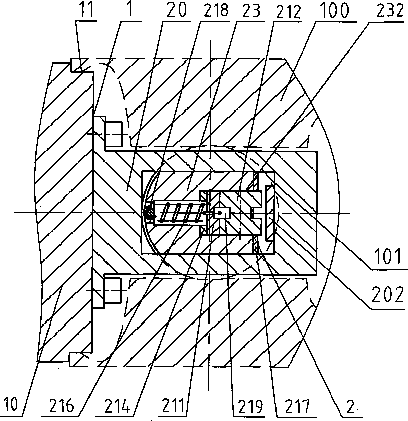
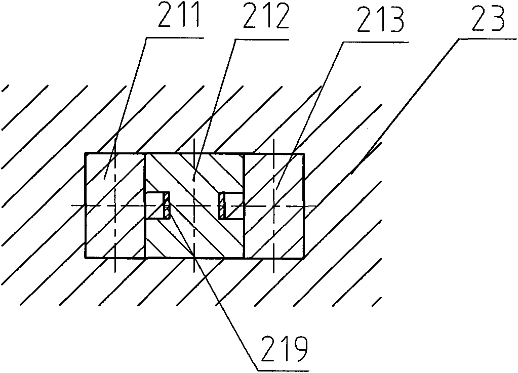
[0018] Such as Figure 1 ~ Figure 4 As shown, the present invention includes a positioning mechanism 1 and a locking mechanism 2. The positioning mechanism 1 includes a positioning tire 10 and a center-through seat 20. The positioning tire 10 of this embodiment is a stepped circular part, and one end thereof is fixed on a lathe fixture 5 The other end is embedded in the inner hole 110 at the bottom of the piston 100 . Piercing seat 20 is a cuboid, and its bottom both sides are fixed on the center of positioning round table 11 of positioning tire 10 by 6 fastening screws, and a rectangular cross hole 201 perpendicular to the axis of threading seat is provided in the middle of threading seat 20 . The locking mechanism 2 includes an elastic clamping mechanism 21, a screw propulsion mechanism 22, and a horizontal pin 23. The horizontal pin 23 is a long shaft member with an...


PUM


Abstract

The invention discloses a piston positioning and locking device, comprising a positioning mechanism and a locking mechanism; wherein the positioning mechanism comprises a positioning tyre and a piercing seat, the locking mechanism comprises an elastic clamp mechanism, a spiral propelling mechanism and a traverse pin. The inner bore at the bottom of the machined piston is sleeved on the positioning tyre. The bottom of the piercing seat is fixed at the other end of the positioning tyre, traverse holes are arranged at the middle part of the piercing seat; the traverse pin respectively penetrates through the piston pin hole of the machined piston and the traverse hole of the piercing seat; the shape of one side of the traverse pin fits the shape of the piston pin hole, a traverse pin hole is arranged at one side of the middle part of the traverse pin hole; the traverse pin hole can penetrate through the bottom of a traverse groove arranged at the other side of the middle part of the traverse pin, one end of the traverse pin is also provided with a longitudinal hole which penetrates through the lateral side of the traverse groove; an elastic clamp system is arranged in the traverse pin hole and the traverse groove while the spiral propelling mechanism is arranged in the in the traverse hole. The arc surface at the left side of the traverse pin fits the locking pistons at the two ends of the piston pin hole. The invention features simple structure, convenient operation, accurate positioning and reliable locking.

Description

technical field [0001] The invention relates to a positioning and locking device for cutting workpieces, in particular to a positioning and locking device for piston processing, which belongs to the technical field of metal cutting. Background technique [0002] The piston is the core part of the diesel engine, its upper part is a solid structure, and the lower part is a hollow thin-walled cylinder with a transverse piston pin hole. During the cutting process of the piston, due to the particularity of the piston material and the technical requirements, the lower hollow thin-walled cylinder is roughly machined first, and then the three ring grooves of the upper solid structure are machined. Due to the poor rigidity of the thin-walled cylinder at the lower part of the piston, clamping the outer circle of the lower part of the piston will cause its plastic deformation, and the piston needs to be aligned, which is inconvenient to operate and affects the machining accuracy of the...

Claims


Application Information

Patent Timeline
Patent Type & Authority Applications(China)
IPC IPC(8): B23Q3/00
Inventor 左原之汝保权
Owner CSSC MARINE POWER
Learn More