
Flue gas denitration reactor

A technology for denitrification reactors and reactor shells, applied in the field of flue gas denitrification reactors with selective catalytic reduction method for internal heat preservation, can solve the problems of rising manufacturing costs, large amount of metal materials, and high heat preservation costs, and achieve increased structural safety , high durability and low manufacturing cost

Inactive Publication Date: 2010-09-15
SOUTHEAST UNIV
View PDF8 Cites 0 Cited by
  • Summary
  • Abstract
  • Description
  • Claims
  • Application Information

AI Technical Summary

Problems solved by technology

[0004] The heat insulation between the flue gas denitrification reactor with external heat preservation and the external environment has a good effect, but the heat preservation structure is relatively complicated, the amount of metal materials is large, and the heat preservation cost is high; at the same time, because the shell of the flue gas denitration reactor It is made of steel, and when it is in direct contact with high-temperature flue gas, its high-temperature enduring strength and creep strength properties will change greatly, which will have a greater impact on the safety of the structural strength of the flue gas denitrification reactor. To ensure the safety of the structure, the flue gas denitrification reactor needs to adopt various structural strengthening measures, which will increase the manufacturing cost

Method used


Image

  • Flue gas denitration reactor
  • Flue gas denitration reactor
  • Flue gas denitration reactor

Examples


Embodiment Construction

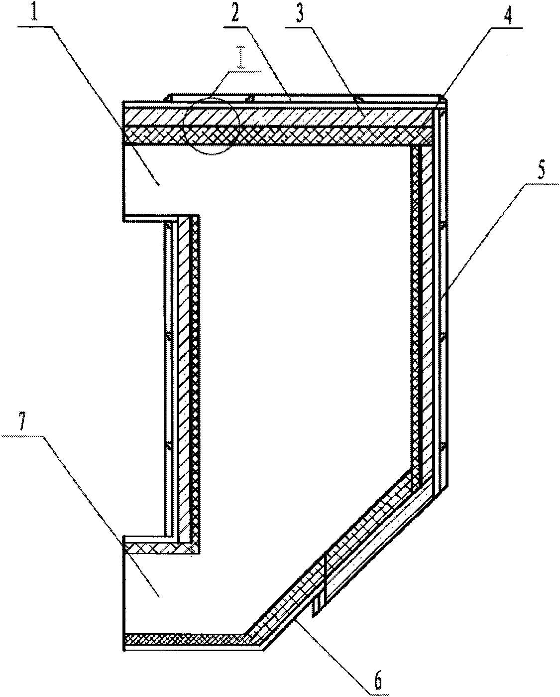
[0014] A flue gas denitrification reactor comprises a shell and an insulating layer laid on the inner wall of the shell.

[0015] Preferably, the flue gas denitration reactor further includes a wear-resistant layer laid on the inner wall of the insulation layer.

[0016] Preferably, the housing includes a side plate, a top plate and an inclined plate respectively connected to the side plates, the top plate and the side plate jointly form a first opening, and the inclined plate and the side plate jointly form a second opening.

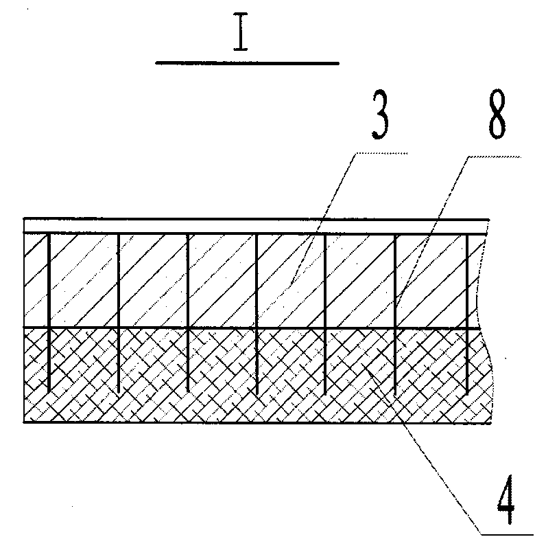
[0017] Preferably, the flue gas denitrification reactor is further provided with heat-resistant steel bars welded to the inner wall of the housing, and the insulation layer is fixed on the heat-resistant steel bars.

[0018] Preferably, the wear-resistant layer is also held on the heat-resistant steel bars.

[0019] see Figure 1 to Figure 2 As shown, the flue gas denitrification reactor of the present invention is applied to the flue gas denitrificat...


PUM


Abstract

The invention relates to a flue gas denitration reactor. An internal layer of a reactor shell is a wear-resisting layer (4); a heat-insulating layer (3) is coated outside the wear-resisting layer (4); the outside of the heat-insulating layer (3) is provided with a lateral plate (5), a top plate (2) and an inclined plate (6); the top plate (2) and the lateral plate (5) form a first opening (1) together on the upper part of the reactor shell; and the inclined plate (6) and the lateral plate (5) form a second opening (7) together on the lower part of the reactor shell. The flue gas denitration reactor is also provided with a heat-resisting steel bar (8) welded on the inner wall of the shell; the heat-insulating layer (3) is fixedly supported on the heat-resisting steel bar (8); the wear-resisting layer (4) is also fixedly supported on the heat-resisting steel bar (8); the heat-insulating layer of the wear-resisting layer is positioned on the inner side of the reactor shell, so that a stressed structure of the shell directly contacts external environment; and the shell is in a state of normal temperature, so that the denitration reactor has the advantages of small high-temperature creep deformation, high durable strength, high structural safety and low manufacturing cost.

Description

technical field [0001] The invention belongs to the technical field of flue gas denitrification equipment manufacturing, and relates to a flue gas denitrification reactor with internal heat preservation selective catalytic reduction method. Background technique [0002] Selective catalytic reduction flue gas denitrification technology is the most widely used flue gas denitrification technology in my country. The core device in the denitrification process using this technology is the flue gas denitrification reactor. Catalysts are installed in the flue gas denitrification reactor. , so that the nitrogen oxides in the flue gas react with the reducing agent into nitrogen and water. Due to the high flue gas temperature of the flue gas denitrification reactor, it is necessary to take thermal insulation measures for the reactor. [0003] The heat preservation method adopted in the flue gas denitrification reactor of selective catalytic reduction method in the related art is the me...

Claims


Application Information

Patent Timeline
Patent Type & Authority Applications(China)
IPC IPC(8): B01D53/86B01D53/56
Inventor 孙克勤沈凯徐海涛周长城
Owner SOUTHEAST UNIV
Learn More