Hydraulic system control device and valve timing control device
A technology of valve timing control and hydraulic system, which is applied in the direction of fluid pressure actuation system components, mechanical equipment, engine control, etc., and can solve problems such as inaccurate estimation of oil viscosity
- Summary
- Abstract
- Description
- Claims
- Application Information
AI Technical Summary
Problems solved by technology
Method used
Image

Examples
no. 1 approach 〗
[0127] will now refer to Figure 1 to Figure 5 A first embodiment of the present invention relating to a valve timing control apparatus for an internal combustion engine (hereinafter simply referred to as an engine) will be described.
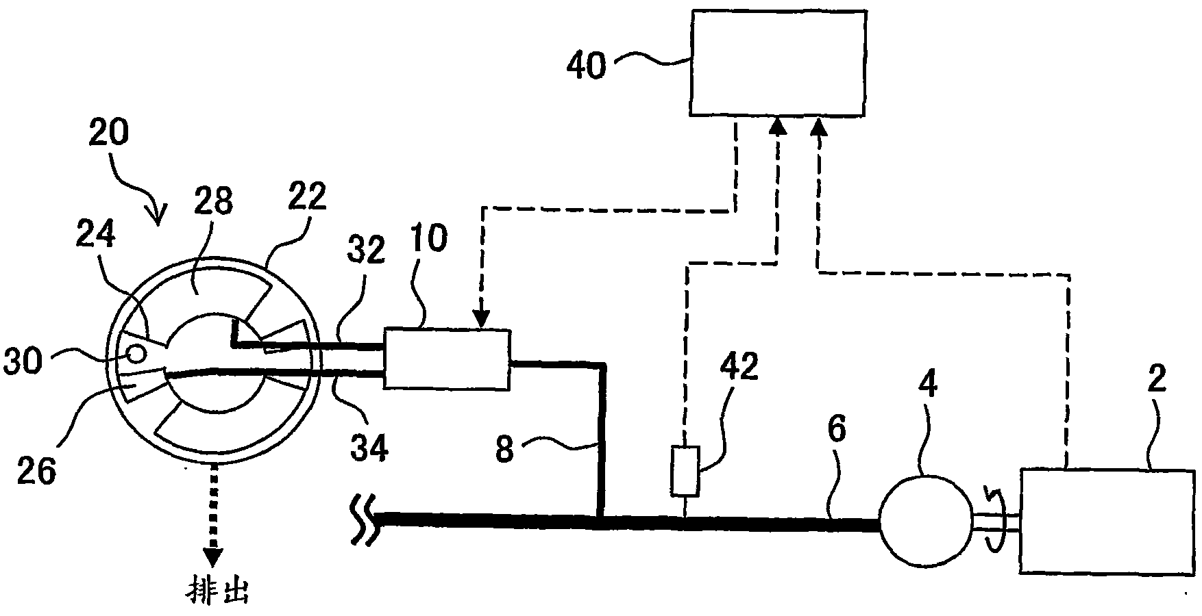
[0128] Can refer to figure 1 The configuration of the valve timing control apparatus according to the first embodiment will be outlined. figure 1 A hydraulic circuit for a valve timing control device applied to an intake valve is shown. As shown in the figure, the valve timing control apparatus includes a variable valve timing mechanism (hereinafter referred to as VVT) 20 as a hydraulic actuator. The VVT 20 includes a housing 22 coupled to the crankshaft by a belt or chain and a vane assembly 24 that rotates with a camshaft located inside the housing 22 .
[0129] Two oil chambers 26 , 28 are formed within the housing 22 and are separated from each other by the vane assembly 24 . The VVT 20 changes the volume ratio between the two oil c...
no. 2 approach 〗
[0166] will now refer to figure 1 and Figure 8 to Figure 11 A valve timing control apparatus according to a second embodiment of the present invention is described.
[0167] The valve timing control apparatus according to the second embodiment includes a hydraulic circuit configured the same as that of the first embodiment. Therefore, the following description assumes that the hydraulic circuits employed are constructed to match those used in the figure 1 The same as in the first embodiment shown.
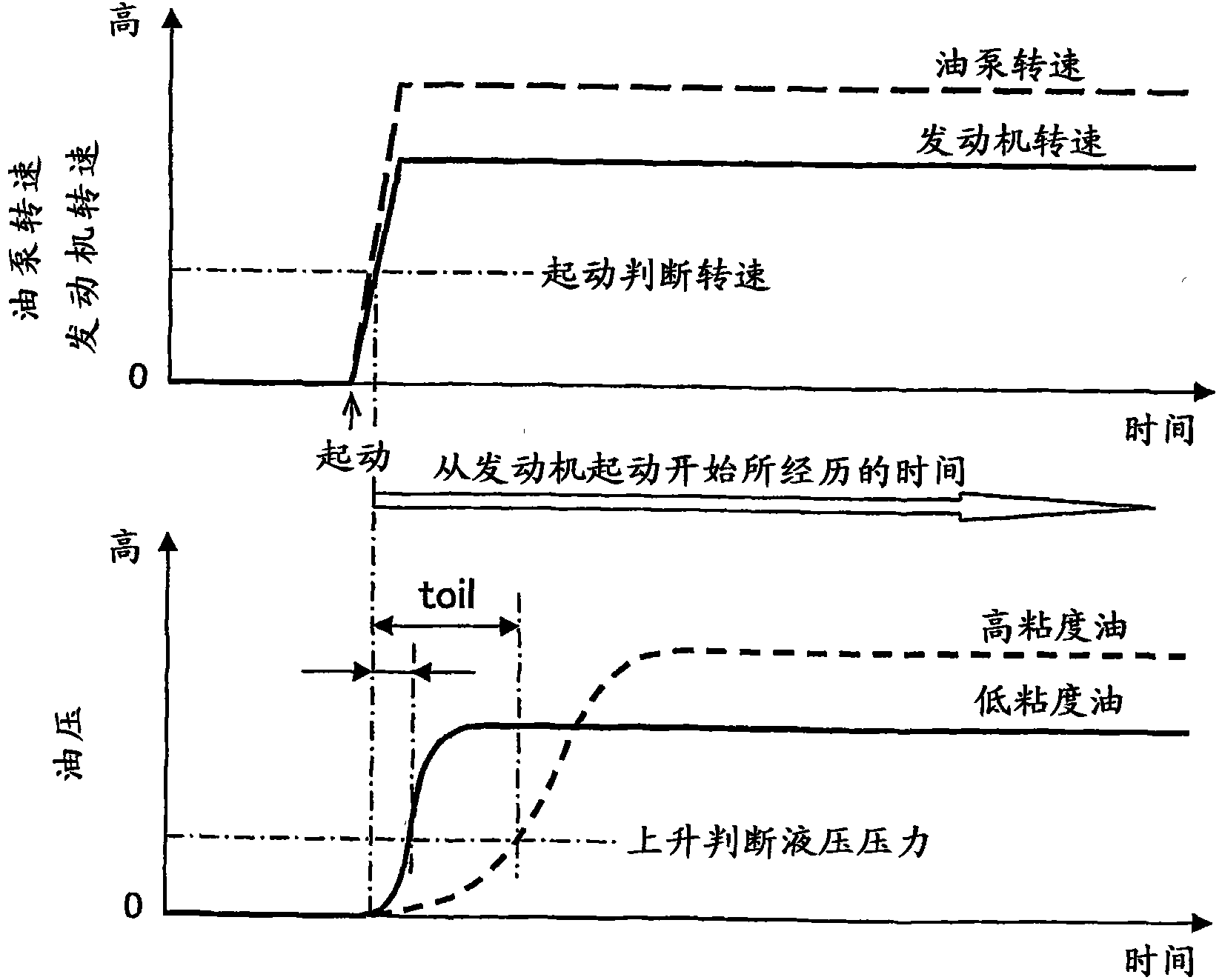
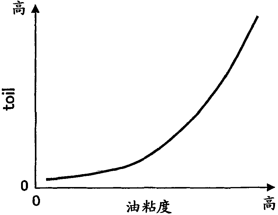
[0168] The valve timing control apparatus according to the second embodiment is similar to the valve timing control apparatus according to the first embodiment in that the oil viscosity is reflected in the operation prohibition time setting of the VVT 20 . However, the difference between the second embodiment and the first embodiment lies in the method of judging the oil viscosity.
[0169] The oil viscosity judging method employed in the second embodiment will now be descri...
no. 3 approach 〗
[0183] will now refer to figure 1 and Figure 12 to Figure 15 A valve timing control apparatus according to a third embodiment of the present invention will be described.
[0184] The valve timing control apparatus according to the third embodiment includes a hydraulic circuit configured the same as that of the first embodiment. Therefore, the following description assumes that the hydraulic circuits employed are constructed to match those used in the figure 1 The same as in the first embodiment shown.
[0185] The valve timing control apparatus according to the third embodiment is similar to the valve timing control apparatuses according to the first and second embodiments in that the oil viscosity is reflected in the operation prohibition time setting of the VVT 20 . However, the third embodiment differs from the first and second embodiments in the method of judging the oil viscosity.
[0186] The oil viscosity judging method employed in the third embodiment will now b...
PUM
 Abstract
Description
Claims
Application Information
 - Generate Ideas
- Intellectual Property
- Life Sciences
- Materials
- Tech Scout
- Unparalleled Data Quality
- Higher Quality Content
- 60% Fewer Hallucinations
Browse by: Latest US Patents, China's latest patents, Technical Efficacy Thesaurus, Application Domain, Technology Topic, Popular Technical Reports.
© 2025 PatSnap. All rights reserved.Legal|Privacy policy|Modern Slavery Act Transparency Statement|Sitemap|About US| Contact US: help@patsnap.com