
Fluorescent lamp electronic ballast and lighting device

A technology for electronic ballasts and fluorescent lamps, which is applied in the field of fluorescent lamp lighting, can solve the problems of easy damage of ballasts and narrow operating voltage range of ballasts, and achieve high efficiency

Inactive Publication Date: 2013-08-28
OCEANS KING LIGHTING SCI&TECH CO LTD +1
View PDF4 Cites 0 Cited by
  • Summary
  • Abstract
  • Description
  • Claims
  • Application Information

AI Technical Summary

Problems solved by technology

[0003] The purpose of the embodiments of the present invention is to provide an electronic ballast for fluorescent lamps, which aims to solve the problem that the existing ballasts are easily damaged due to the narrow operating voltage range

Method used


Image

  • Fluorescent lamp electronic ballast and lighting device
  • Fluorescent lamp electronic ballast and lighting device
  • Fluorescent lamp electronic ballast and lighting device

Examples


Embodiment Construction

[0013] In order to make the object, technical solution and advantages of the present invention clearer, the present invention will be further described in detail below in conjunction with the accompanying drawings and embodiments. It should be understood that the specific embodiments described here are only used to explain the present invention, not to limit the present invention.

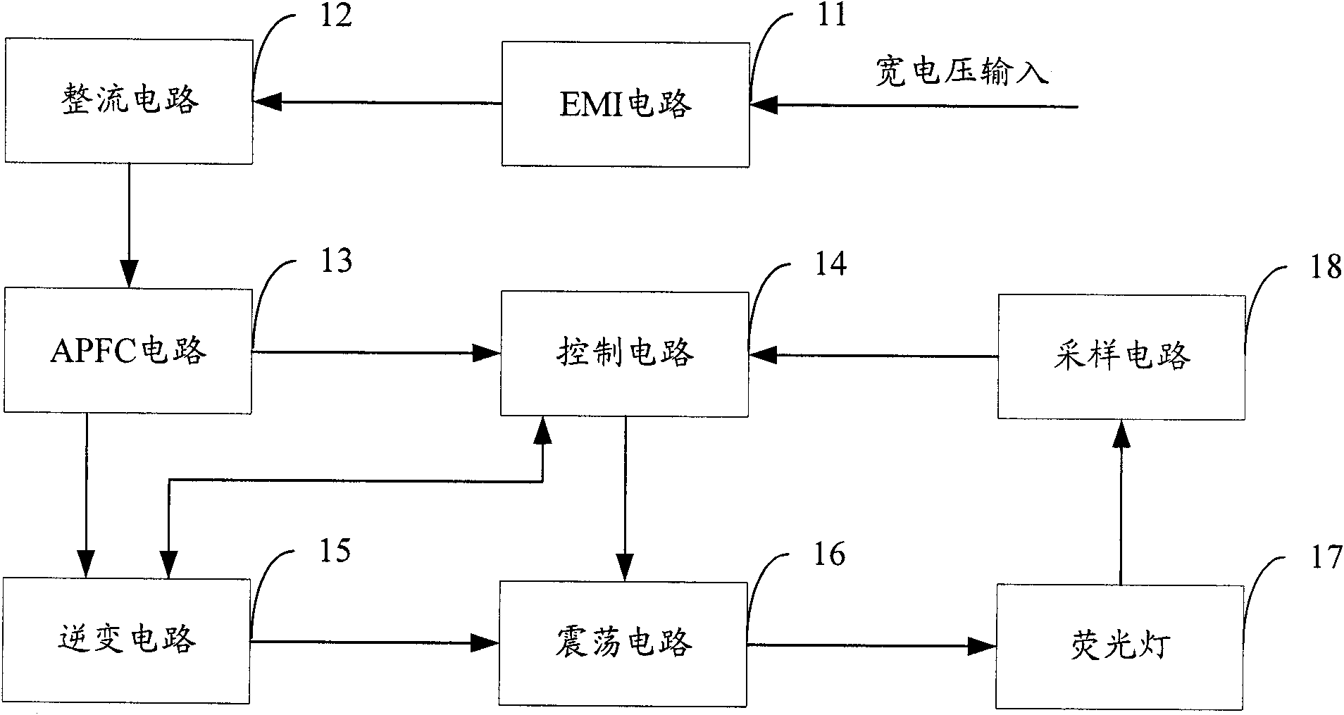
[0014] The electronic ballast for fluorescent lamps provided by the embodiment of the present invention adopts an active power factor correction circuit combined with a control circuit and a sampling circuit to widen the conduction angle of the input circuit, so that the electronic ballast can work stably within a wide voltage range of 85V to 300V .

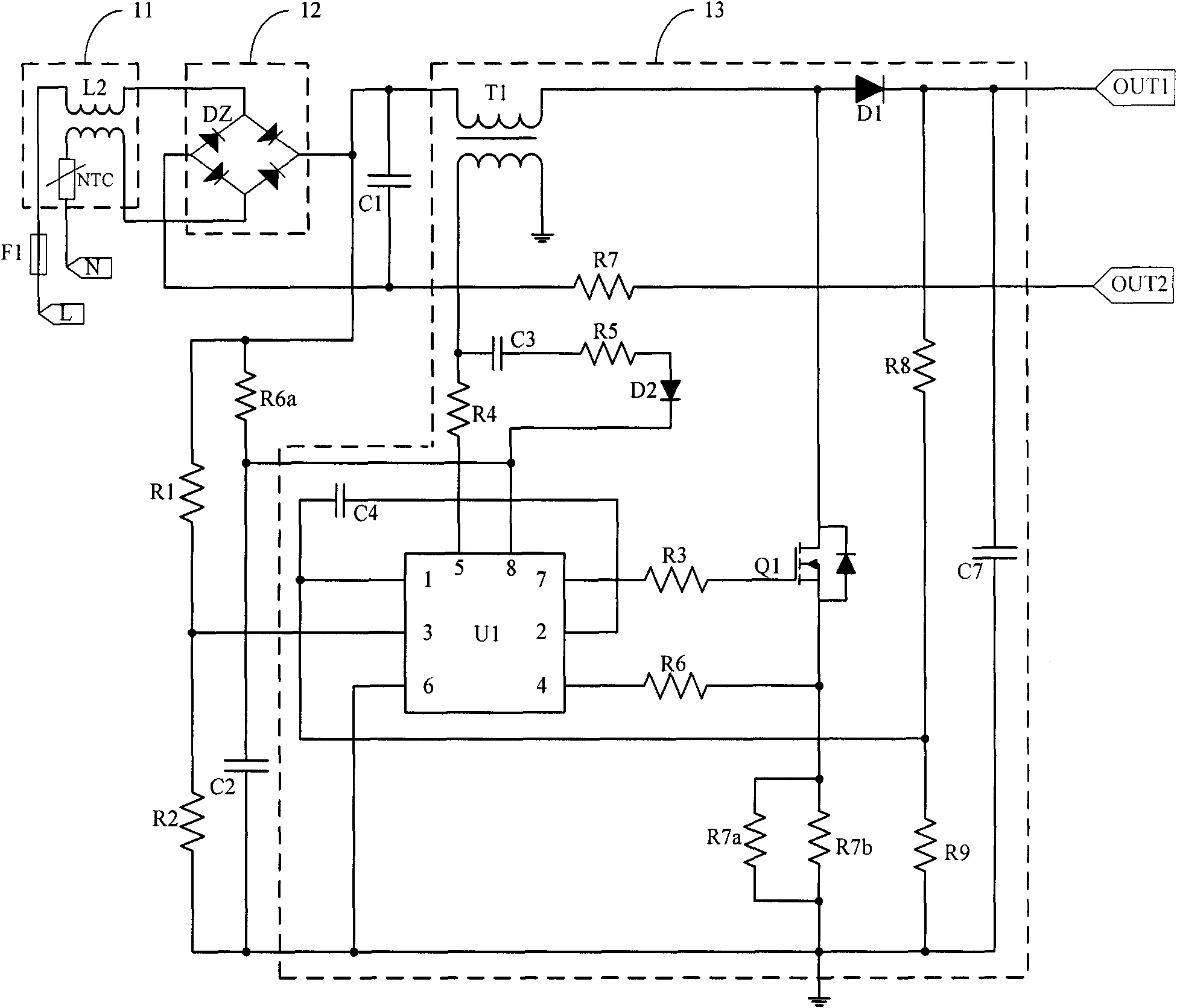
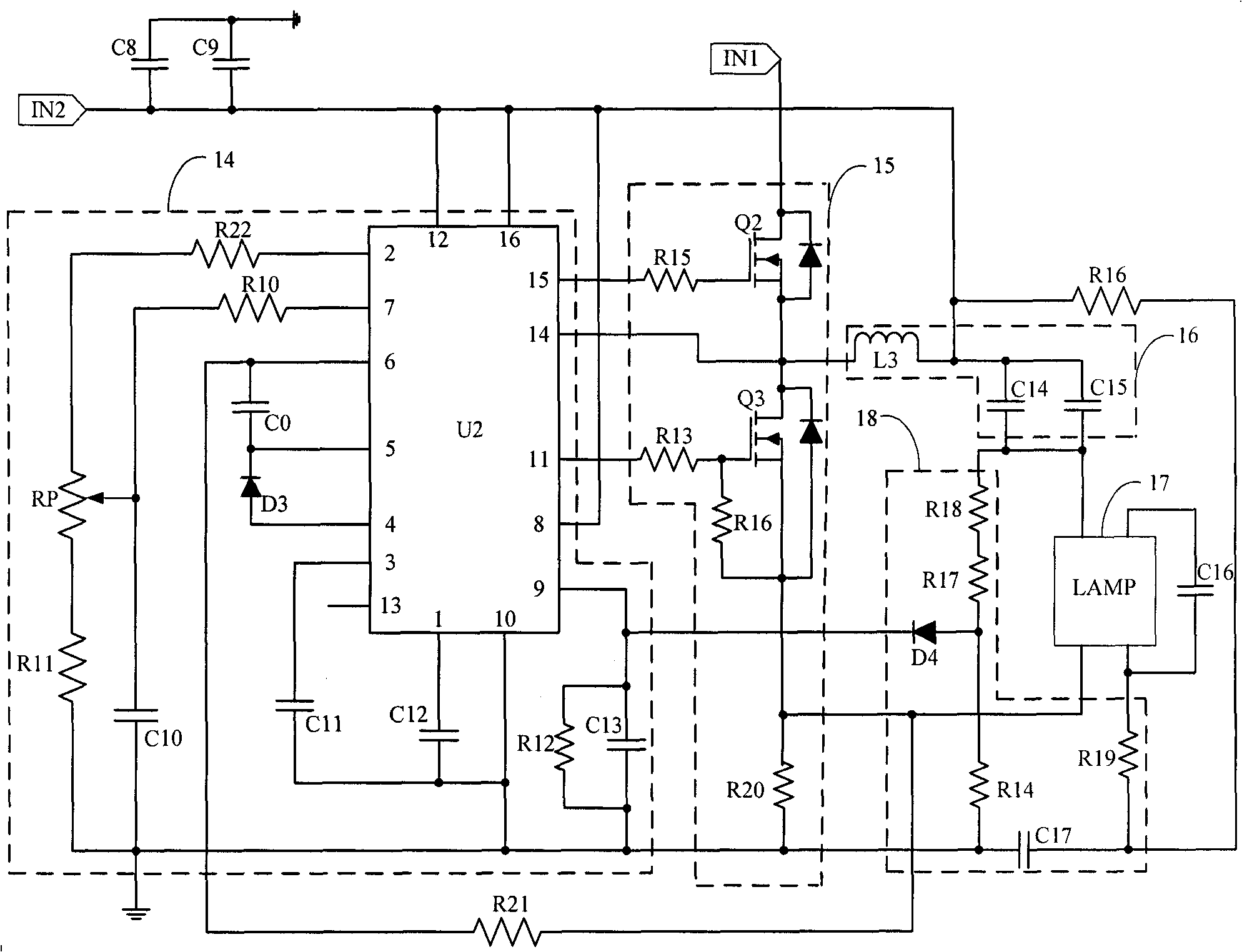
[0015] The electronic ballast for fluorescent lamps with wide voltage input provided by the embodiment of the present invention is mainly used in lighting devices. The schematic diagram of its module structure is as follows: figure 1 As shown; for th...


PUM


Abstract

The invention is applicable to the field of fluorescent lamp lighting, and provides a fluorescent lamp electronic ballast and a lighting device; the fluorescent lamp electronic ballast comprises an EMI circuit, a rectifying circuit, an oscillating circuit, an inverting circuit, an active power factor correction circuit, a control circuit and a sampling circuit, wherein the input end of the activepower factor correction circuit is connected to the output end of the rectifying circuit, and a first output end is connected to the input end of the inverting circuit; the input end of the sampling circuit is connected with a fluorescent lamp and carries out sampling on working current of the fluorescent lamp; and the sampling end of the control circuit is connected to the output end of the sampling circuit, the input end thereof is connected to a second output end of the active power factor correction circuit, the output end thereof is connected to the control end of the oscillating circuit, and the control end thereof is connected to the control end of the inverting circuit. The electronic ballast provided by the invention adopts the active power factor correction circuit, and leads a conduction angle of an input circuit to be widened by combining the control circuit and the sampling circuit, thus leading the electronic ballast to work stably in the wide voltage range of 85V-300V.

Description

technical field [0001] The invention belongs to the field of fluorescent lamp lighting, in particular to an electronic ballast for fluorescent lamps and a lighting device. Background technique [0002] After the mains input, the traditional electronic ballasts for fluorescent lamps are directly output after EMI circuit, rectification, and inversion; although they can work, there are also some defects: (1) There is only one mains 220V input, if in some remote If the regional voltage is less than 220V (such as only 150V or 160V), the ballast may not be able to start; or when the voltage is too high to 250V or higher, the switch tube and related capacitors used in the ballast may not be able to withstand the withstand voltage and cause (2) There is no relevant protection circuit, once short-circuited, it may cause the lamp to go out, and in severe cases, it may cause fire and smoke, which poses a safety hazard; (3) The ballast current designed for this type of circuit The harm...

Claims


Application Information

Patent Timeline
Patent Type & Authority Patents(China)
IPC IPC(8): H05B41/298
Inventor 周明杰姚泉
Owner OCEANS KING LIGHTING SCI&TECH CO LTD
Learn More