Capacitance apparatus and system for measuring high voltage element voltage and gas insulated transformer substation

A technology of high-voltage components and capacitive equipment, which is applied in the direction of measuring electrical variables, measuring current/voltage, measuring devices, etc., to achieve the effect of low cost

Inactive Publication Date: 2015-01-07
ALSTOM TECH LTD
View PDF7 Cites 0 Cited by
  • Summary
  • Abstract
  • Description
  • Claims
  • Application Information

AI Technical Summary

Problems solved by technology

Furthermore, such equipment must be selective: if there is more than one conductor, the measurement signal must depend primarily on the conductor being monitored, with less than 10% influence due to other conductors

Method used


Image

  • Capacitance apparatus and system for measuring high voltage element voltage and gas insulated transformer substation
  • Capacitance apparatus and system for measuring high voltage element voltage and gas insulated transformer substation
  • Capacitance apparatus and system for measuring high voltage element voltage and gas insulated transformer substation

Examples


Embodiment Construction

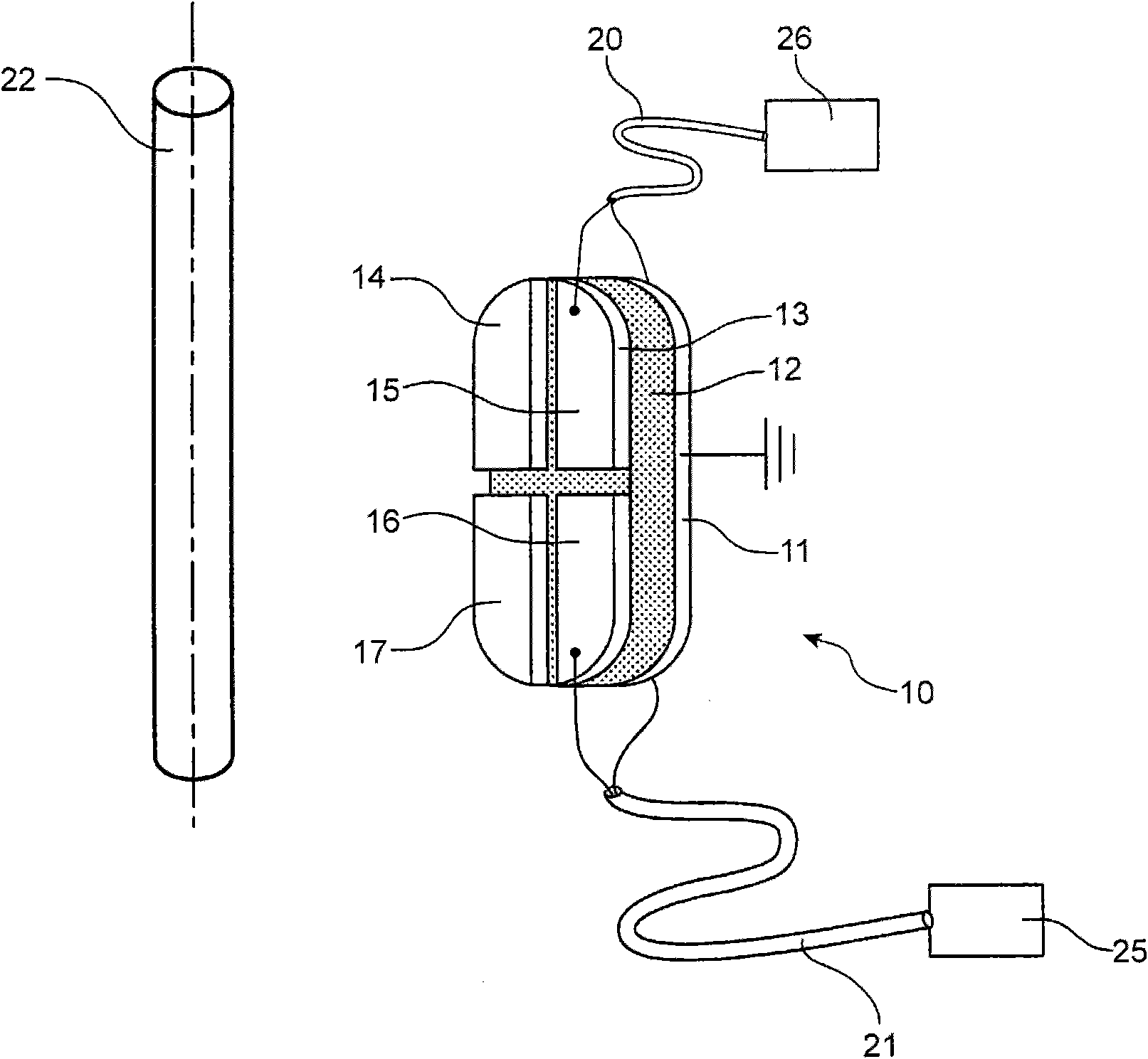
[0056] The device 10 of the present invention, such as figure 1 shown, consists of a printed circuit board consisting of three layers:

[0057] a first layer 11 is a conductive layer;

[0058] a second layer 12, made of insulating material, preferably epoxy, with a thickness of very high precision; and

[0059] A third layer 13 is a conductive layer.

[0060] The third layer 13 includes a plurality of conductive parts, such as figure 1 Four sections 14 , 15 , 16 and 17 are shown, each of which is arranged to be connected to at least one of two signal output cables 20 and 21 .

[0061] This first layer 11 is usually connected to ground potential. The third layer 13 faces a high voltage electrode 22, for example a conductor whose high voltage is to be measured. Due to the influence of the electric field generated by the high voltage electrode 22, this third layer 13 is connected to a voltage level slightly higher than ground potential.

[0062] The device 10 of the present...


PUM


Abstract

#CMT# # / CMT# The device (10) has an oblong printed circuit board including an insulating layer (12) and a conductive layer (11) connected to ground potential. The printed circuit board has another conductive layer (13) formed of separated conductor sectors (14-17) that are connected in parallel to a control equipment (25) and an optical luminous display (26) i.e. LED display, via signal output cables (20, 21), respectively. The printed circuit board has contact bridges that connect the conductor sectors to the corresponding signal output cables. #CMT# : # / CMT# An independent claim is also included for a gas insulated electric substation comprising a capacitive device for measuring voltage of a high voltage element. #CMT#USE : # / CMT# Capacitive device for measuring voltage of a high voltage element e.g. high voltage electrode such as high voltage conductor, in an inner surface of a metal case of a grounding switch of a gas insulated electric substation (claimed) i.e. three phase sulfur hexafluoride insulated electric substation. #CMT#ADVANTAGE : # / CMT# The device measures the voltage of the high voltage element in a simple and reliable manner. The device can be fabricated in an inexpensive manner. The device has reduced encumbrance and is small in size so as to permit the device to be installed in the substation in an easy manner. The device is configured such that the circuit board is changed to easily adjust the characteristics and transmission rate of the device to obtain voltage and current of the high voltage element for different operating conditions of applications. The printed circuit board is oblong so as to create redundancy of information in an easy manner and to reduce the distortion of a measurement signal for specific utilization in the substation. The configuration of the device permits supply of power to the display without requiring an exterior energy source. The device can be occupied in less space. #CMT#DESCRIPTION OF DRAWINGS : # / CMT# The drawing shows a perspective view of a capacitive voltage measuring device and a high voltage element. 10 : Capacitive voltage measurement device 11, 13 : Conductive layers 12 : Insulating layer 14-17 : Conductor sectors 20, 21 : Signal output cables 25 : Control equipment 26 : Optical luminous display #CMT#INDUSTRIAL STANDARDS : # / CMT# The device is connected to a voltage detection system based on International Electrotechnical Commission (IEC) 61243-5standard.

Description

technical field [0001] The present invention relates to a capacitive device and system for measuring the voltage of a high-voltage component, and a gas-insulated substation using the capacitive device. Background technique [0002] The field of the invention is that of measuring the voltage of high voltage components. This field refers in particular to capacitive devices designed for use in shielded electrical equipment, as well as insulating substances provided in gaseous form, such as sulfur hexafluoride (sulfur hexafluoride) or SF 6 . [0003] This device can be used to measure the voltage of a busbar carrying a current in a Metal Composite Switcher (MCS) or Gas Insulated Substation (GIS). The equipment must meet the following criteria: it must be simple and reliable, it must be able to be manufactured at low cost, it must take up little space, and it must be a dual Remain. Furthermore, the characteristics of the device, especially its transfer ratio, must be easily a...

Claims


Application Information

Patent Timeline
Patent Type & Authority Patents(China)
IPC IPC(8): G01R19/00
CPCG01R15/165H02B13/0356
Inventor 罗伯特·吕舍尔卡斯腾·波林克雨果·希尔特布龙纳赫拉尔多·帕尔米耶
Owner ALSTOM TECH LTD
Why Eureka
Try Eureka