
Kitchen ventilation system and control method

A technology for ventilation systems and kitchens, applied in the field of ventilation systems, can solve problems such as damage to baffles and valves, energy waste, and increased power consumption of motors

Inactive Publication Date: 2010-09-08
马洪刚
View PDF3 Cites 3 Cited by
  • Summary
  • Abstract
  • Description
  • Claims
  • Application Information

AI Technical Summary

Problems solved by technology

[0004] 1. It is impossible to adjust the processing flow of the fan according to the number of stoves turned on; when only one or a few stoves are in use in each system, and the fans in the system are operating at full capacity, it will cause energy loss. great waste;
[0005] 2. It is impossible to intelligently adjust the flow rate of each valve according to actual needs;
[0006] 3. When the motor cannot run at full load, in addition to meeting the driving requirements, the excess torque of the motor increases the power consumption, resulting in a waste of electric energy; at the same time, because the air volume of the fan is mechanically adjusted through the baffle or valve, a large amount of energy is absorbed by the baffle And valves go to waste;
[0007] 4. The hard start of the motor will cause a serious impact on the power grid, and it will also require too high a capacity of the power grid. When starting a large current and vibration, the damage to the baffle and the valve will be great, and it will be unfavorable to the service life of the equipment and pipelines. influences

Method used


Image

  • Kitchen ventilation system and control method
  • Kitchen ventilation system and control method
  • Kitchen ventilation system and control method

Examples


Embodiment Construction

[0049] Example 1 of Kitchen Ventilation System

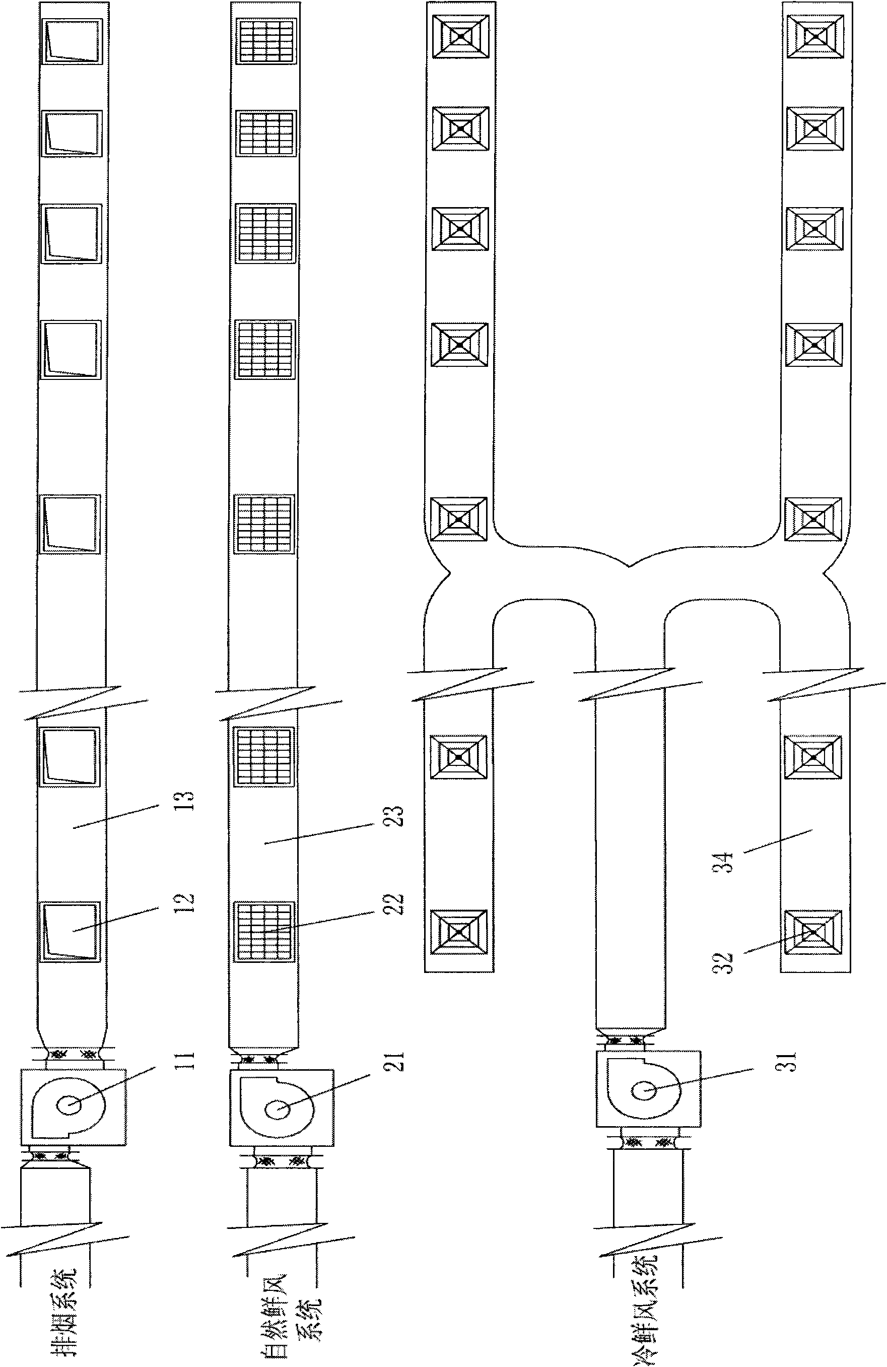
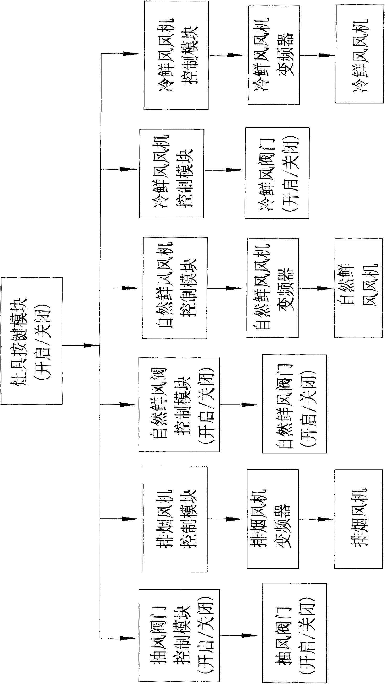
[0050] Such as figure 1 , figure 2 As shown, the kitchen ventilation system of the present invention includes a smoke exhaust system, a natural fresh air system, a cold fresh air system and a cooker button module.

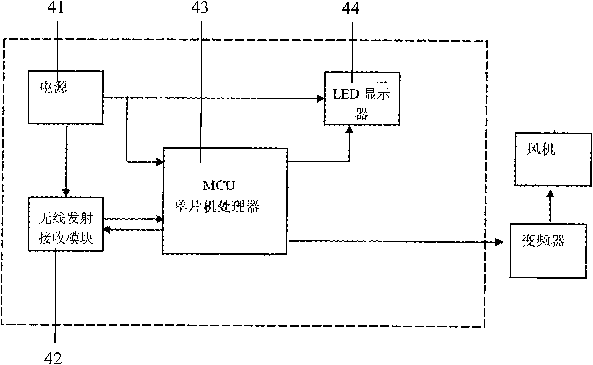
[0051] The smoke exhaust system includes a smoke exhaust flue 13, an exhaust valve 12 arranged at each exhaust point on the smoke exhaust flue 13, a smoke exhaust fan 11 arranged at the air outlet of the smoke exhaust flue 13, a smoke exhaust fan control module, and an exhaust valve control module. modules and frequency converters for smoke exhaust fans. The input end of the smoke exhaust fan inverter is connected to the power supply, and the output end is connected to the input end of the smoke exhaust fan to realize speed regulation. The smoke exhaust fan control module is connected to the smoke exhaust fan inverter by wire to realize speed regulation control. Signal connection refers to the connection of sign...


PUM


Abstract

The invention discloses a kitchen ventilation system and a control method. The system comprises a smoke exhaust system, a fresh air system, a smoke exhaust fan control module, a smoke exhaust fan frequency converter, an air draft valve control module, a fresh air fan control module, a fresh air fan frequency converter, a fresh air valve control module and a cooker key module, wherein the cooker key module is in signal connection with the smoke exhaust fan control module, the air draft valve control module, the fresh air fan control module and the fresh air valve control module; the air draft valve control module and the fresh air valve control module determine the opening or closing of the valve according to a control signal from the cooker key module; and the smoke exhaust fan control module and the fresh air fan control module determine the frequency conversion control over a corresponding frequency converter according to the control signal of the cooker key module. The method realizes the control over the opening and closing of the valve and the matching of the flow rate of the fan. The system and the method realize the matching of the ventilation volume of the fan and the ventilation volume for actual demand through the frequency modulation control of the fan so as to achieve obvious energy saving effect and effectively prolong the service life of devices and pipelines of the ventilation system.

Description

technical field [0001] The invention relates to a ventilation system and a control method of the ventilation system, in particular to a kitchen ventilation system and a control method. Background technique [0002] The ventilation system of existing large kitchens (such as restaurant kitchens, hotel kitchens, etc.) usually includes a smoke exhaust system, a fresh air system and a cold fresh air system. According to the situation, one or several independent smoke exhaust systems, For the fresh air system and the cold fresh air system, each independent system has one or several fans for exhaust or air intake, which discharges the cooking fume produced by the kitchen stove outside or takes outdoor fresh air into the room. [0003] The existing kitchen ventilation system has the following defects: [0004] 1. It is impossible to adjust the processing flow of the fan according to the number of stoves turned on; when only one or a few stoves are in use in each system, and the fan...

Claims


Application Information

Patent Timeline
IPC IPC(8): F23J11/02F24F7/06
Inventor 马洪刚
Owner 马洪刚
Learn More