
Electric operating mechanism of high-voltage isolating switch

A technology of high-voltage isolating switch and electric operation, which is applied to the power device inside the switch, air switch parts and other directions, and can solve the problems of shortening and increasing the appearance beauty

Inactive Publication Date: 2010-09-01
SHENYANG CHENGLIANHONG ELECTRIC APPLIANCE MFG
View PDF8 Cites 13 Cited by
  • Summary
  • Abstract
  • Description
  • Claims
  • Application Information

AI Technical Summary

Problems solved by technology

[0004] The purpose of the present invention is to provide a special electric operating mechanism for high voltage isolating switches, which fundamentally solves the problems of limited application of the electric operating mechanism and the potential safety hazards in the on-site welding of the output shaft and the operating rod of the isolating switch. In addition to retaining the advantages of manual and electric opening and closing synchronization of the existing electric operating mechanism, it also has the characteristics of reasonable design, labor-saving manual operation, compact structure, small occupied space, and convenient maintenance. The connection of the moving rod does not require on-site welding, which increases the safety and reliability of on-site installation operations, further shortens the opening and closing time of the isolating switch, improves the stability of opening and closing operations, prolongs the service life of the isolating switch, and significantly increases its overall performance. aesthetic appearance

Method used


Image

  • Electric operating mechanism of high-voltage isolating switch
  • Electric operating mechanism of high-voltage isolating switch
  • Electric operating mechanism of high-voltage isolating switch

Examples


Embodiment Construction

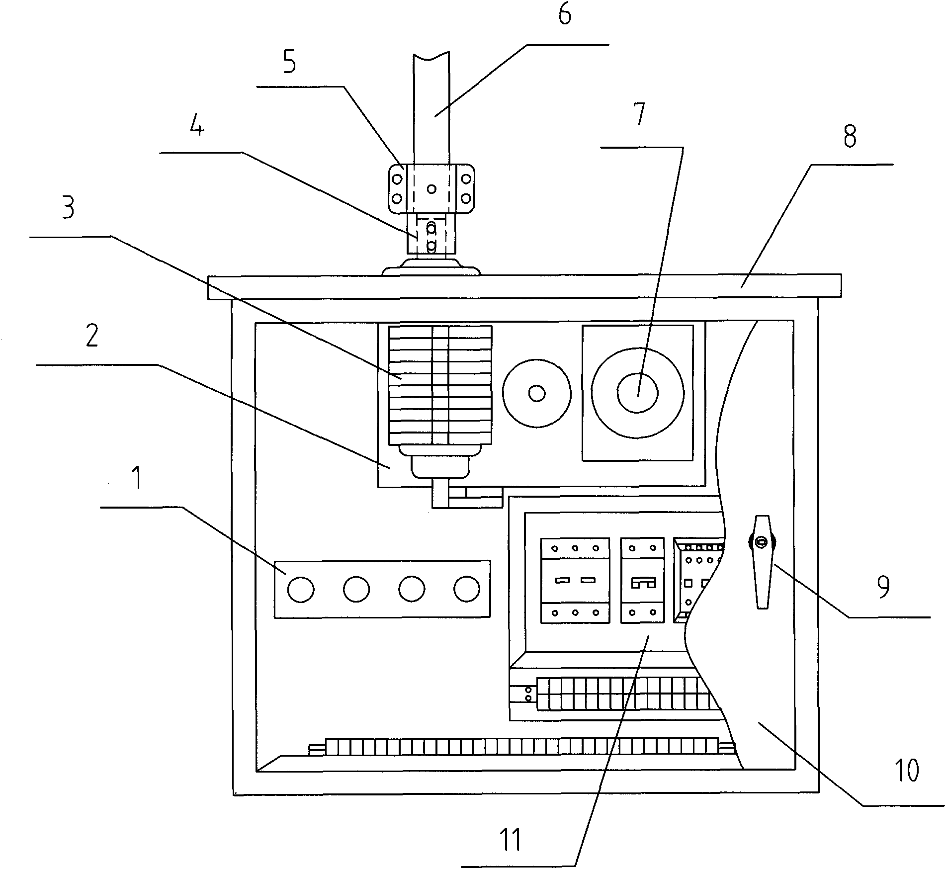
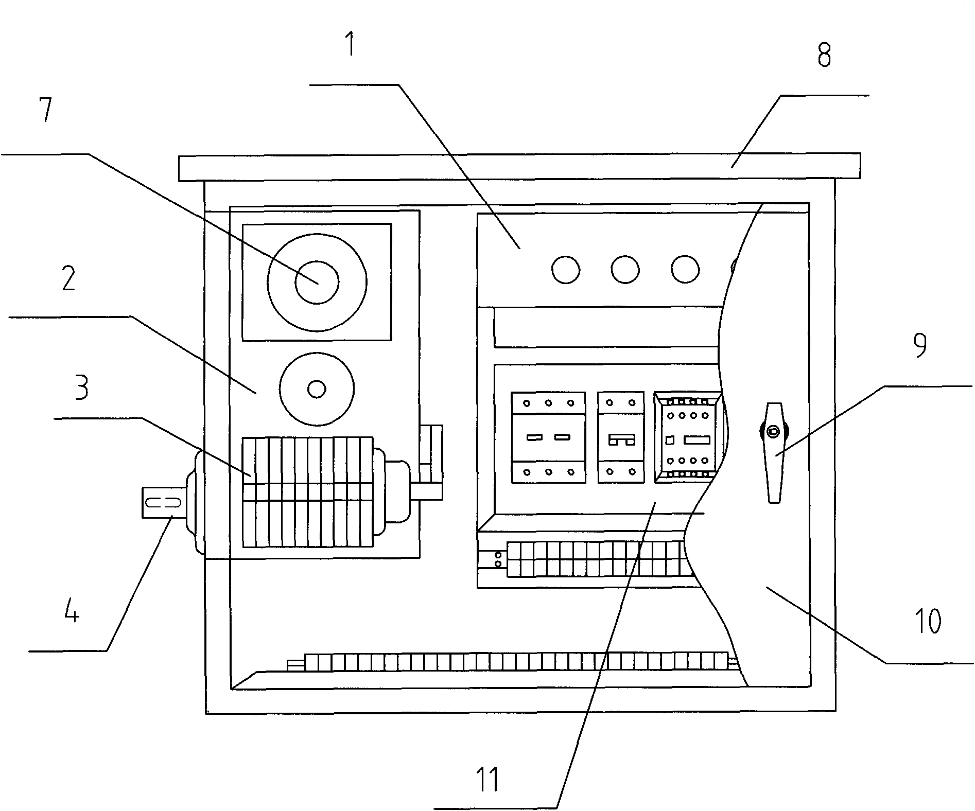
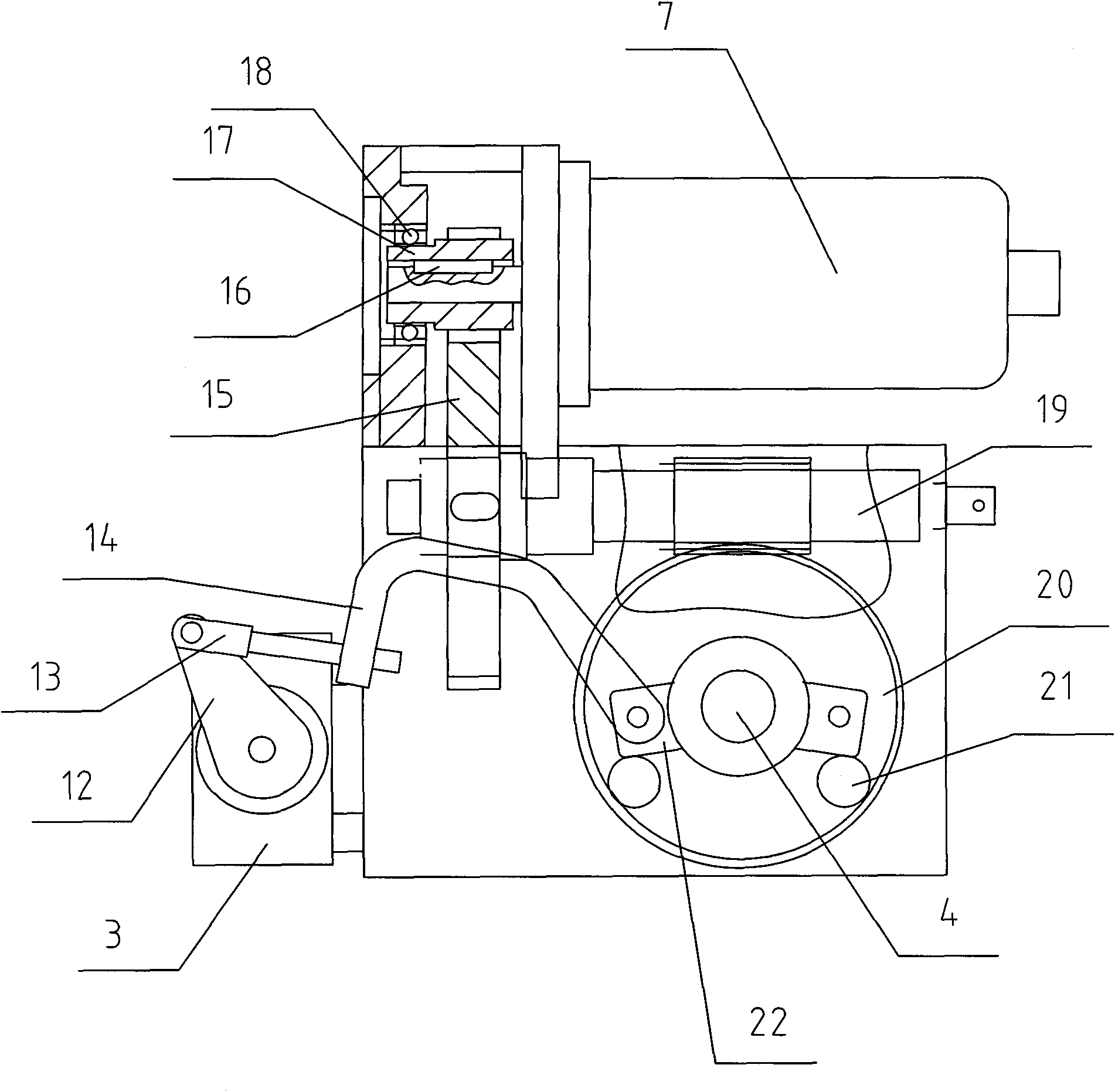
[0017] according to Figure 1~6 The specific structure of the present invention will be described in detail. The electric operating mechanism of the high-voltage isolating switch includes a box body 8 with a mechanism output shaft 4 connected with an isolating switch operating rod 6 and a mechanical transmission device 2 in the assembled box body, an electrical control device, and a manual-electric electric locking device, etc. . Among them, the electrical control device and the manual-electric electrical locking device are still the basic structure of the inventor's previous patent "Outdoor AC High Voltage Isolating Switch Electric Operating Mechanism". The mechanical transmission device 2 is configured as a two-stage transmission mechanism with a compact structure, that is, the first-stage transmission is constituted by the meshing gear sleeve 17 and the large gear 15; the second-stage transmission is constituted by the meshing worm shaft 19 and the worm gear 20. The first-...


PUM


Abstract

The invention relates to an electric operating mechanism of a high-voltage isolating switch, fundamentally solving the problems of potential safety hazards and the like existing in the field welding of an output shaft and an isolating switch operating rod. The electric operating mechanism of a high-voltage isolating switch comprises a tank body as well as a mechanical driving device, an electric appliance control device and a manual-electric electrical locking device which are assembled in the tank body. The electric operating mechanism has the technical essential that a gear sleeve and a large gear which are meshed with each other form primary speed change in the mechanical driving device, the gear sleeve is fixed on an output shaft of an electric motor, a worm shaft and a worm gear which are meshed with each other form secondary speed change, one end of the worm shaft arranged in parallel to the output shaft of the electric motor is fixed with the large gear, and the end of a mechanism output shaft fixed on a worm gear, extending out of the tank body, is connected with the isolating switch operating rod through a semi-subdivision type connecting sleeve. The electric operating mechanism has the advantages of reasonable design, labor saving of manual operation, compact structure, small volume and convenient maintenance, and the mechanism output shaft and the isolating switch operating rod do not need to be welded in a field so that the safety and the reliability of field installation operations are increased, thereby obviously increasing the integral beautiful appearance of the electric operating mechanism.

Description

Technical field [0001] The invention relates to an improved electric operating mechanism, in particular to a high-voltage isolating switch electric operating mechanism with compact structure, beautiful appearance, safe on-site installation, convenient maintenance, and stable opening and closing operation. It belongs to the field of high-voltage electrical equipment. Background technique [0002] With the large increase in unmanned substations and substations of the National Grid, the electric operating mechanism for opening and closing high-voltage isolating switches widely used in power systems, especially the electric motor as the main operating power, makes the high-voltage isolating switch action respond The demand for rapid electric operating mechanisms is also increasing. Therefore, not only the manual operation function is required, but also higher requirements are put forward for the performance and appearance of these electric operating mechanisms. [0003] As we all know...

Claims


Application Information

Patent Timeline
IPC IPC(8): H01H31/02H01H3/26
Inventor 刘若松李长福
Owner SHENYANG CHENGLIANHONG ELECTRIC APPLIANCE MFG
Learn More