
Miniature gas turbine combustion chamber

A micro gas turbine, combustion chamber technology, applied in the combustion chamber, continuous combustion chamber, combustion method and other directions, to achieve the effect of small length, simple gas path and light weight

Active Publication Date: 2010-09-01
BEIHANG UNIV
View PDF3 Cites 76 Cited by
  • Summary
  • Abstract
  • Description
  • Claims
  • Application Information

AI Technical Summary

Problems solved by technology

For micro gas turbines using centripetal turbines, the disadvantages of these two combustors will be more

Method used


Image

  • Miniature gas turbine combustion chamber
  • Miniature gas turbine combustion chamber
  • Miniature gas turbine combustion chamber

Examples


Embodiment Construction

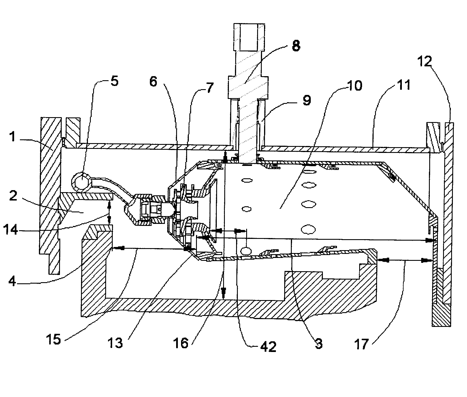
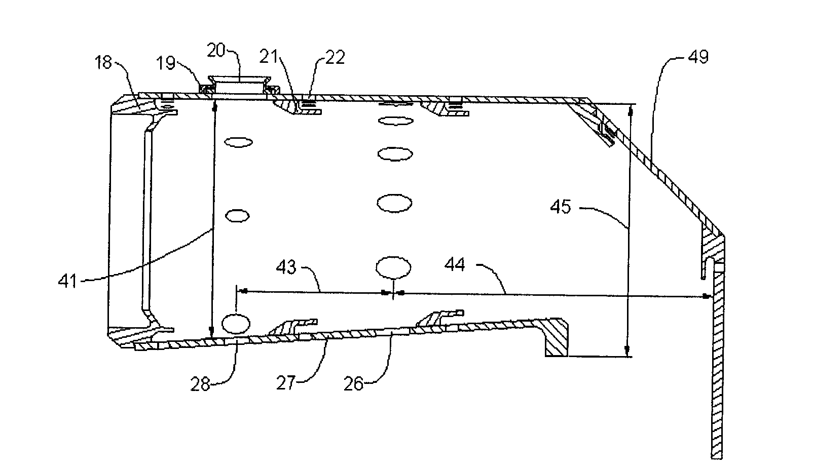
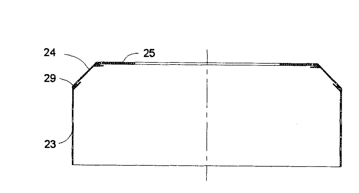
[0030] Such as figure 1As shown, the embodiment of the present invention adopts a ring structure, which is mainly composed of a flame tube 10 , an outer casing 11 , an inner casing 4 , a swirler 7 and a fuel supply system 5 . The flame tube 10 is welded by the outer flame tube 49, the head end wall 18 and the inner flame tube 27, and the distance between the outer flame tube flat section 23 and the inner flame tube 27 is the flame tube height 41. Screw connection is adopted between the vertical section 25 of the outer flame tube and the rear flange 12 of the combustion chamber casing. The rear end of the outer casing 11 is bolted to the rear flange 12 of the casing, and the front flange 1 of the casing is connected to the front end of the casing 11 by bolts. The inlet 2 of the combustion chamber is welded on the front flange 1 of the casing, and is connected with the flow of the centrifugal compressor, and the air enters radially. The spigot fits between the inner casing 4 f...


PUM


Abstract

The invention discloses a miniature gas turbine combustion chamber, which has an annular structure and mainly comprises a flame tube, an outer casing, an inner casing, a swirler and a fuel oil supply system. The flame tube is formed by welding an outer flame tube, a head end wall and an inner flame tube; the rear end of the flame tube is connected with a rear flange of the casing of the combustion chamber through a screw; the rear end of the outer casing is connected with the rear flange of the casing through a bolt; and a front flange of the casing is connected with the front end of the casing through a bolt. An inlet of the combustion chamber is welded on the front flange of the casing; air radially enters the inlet of the combustion chamber; the front end of the inner casing is fixed in a hole of the inlet of the combustion chamber; the swirler is welded on the head end wall; the fuel oil supply system is fixed on an outer ring of the inlet of the combustion chamber; a main combustion hole, a mixing hole and an air film cooling hole are formed on the flame tube; and an air film slot tongue is welded on the lower part of the air film cooling hole for guiding cooling airflow. A high-energy DC igniter is inserted into the flame tube for realizing ignition starting of the totally annular combustion chamber; and gas is discharged out of the combustion chamber radially under the guiding of a slope of the outer flame tube and a vertical section of the outer flame tube. The miniature gas turbine combustion chamber is applied to a miniature gas turbine. Because the gas at the outlet directly impacts a centripetal turbine, the axial distance of the miniature gas turbine can be shortened, and the space is fully utilized.

Description

technical field [0001] The invention relates to a combustion chamber of a gas turbine, in particular to an annular combustion chamber of a micro gas turbine. Background technique [0002] There are three typical types of combustors, which are single-tube combustors, ring-tube combustors and annular combustors. Single-tube combustors are relatively mature in technology due to their early application, less development time and funds, but independent Single-barreled flame barrels and single-barreled receivers result in long lengths and heavy weights and require cross-fired tubes. When a single-tube combustor is applied to a micro gas turbine, it needs to be installed outside the axis of the compressor and the turbine, and the air flow needs to turn several times, resulting in a large loss. The ring tube combustor puts multiple combustion chambers in a common casing, which is lighter and shorter than the single tube combustor, but it is not easy to match the air flow pattern, e...

Claims


Application Information

Patent Timeline
IPC IPC(8): F23R3/52F23R3/42F23R3/28
Inventor 张弛王建臣林宇震许全宏
Owner BEIHANG UNIV
Learn More