Planetary gear differential power plant
A planetary gear differential and power device technology, which is applied in the direction of machines/engines, rotary piston engines, rotary or swinging piston engines, etc., can solve the problems of high eccentric vibration, high transmission efficiency, and low efficiency, and achieve small eccentric vibration force, The effect of low material requirements and high transmission precision
- Summary
- Abstract
- Description
- Claims
- Application Information
AI Technical Summary
Problems solved by technology
Method used
Image
Examples
Embodiment 1
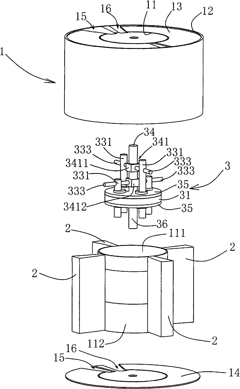
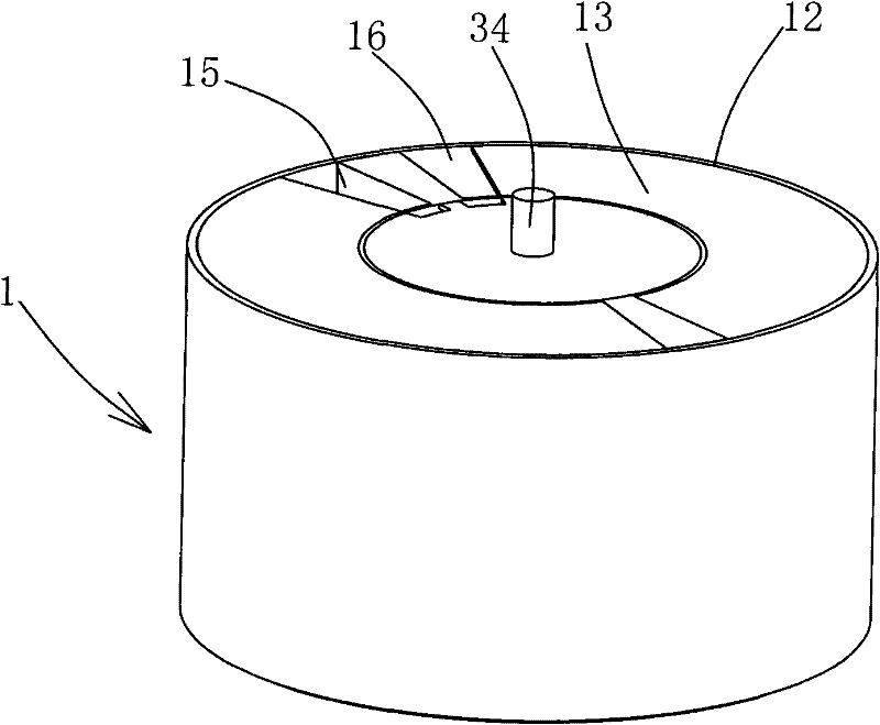
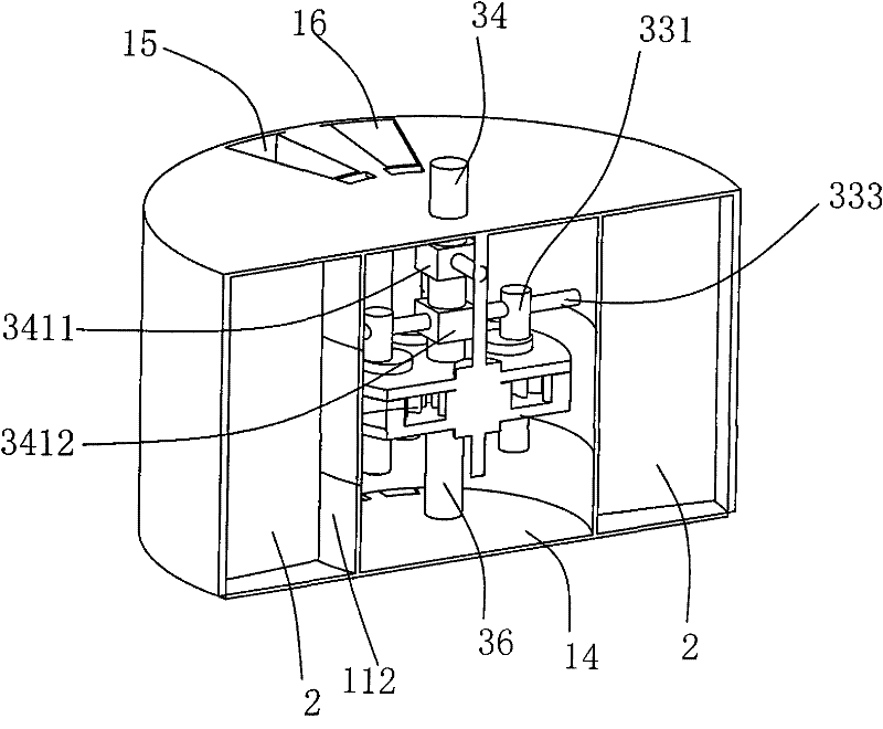
[0025] See Figure 1 to Figure 4 , Figure 1 to Figure 4 It is a structural schematic diagram of an embodiment of the present invention.
[0026] It is a planetary gear differential power device, including a cylinder 1, at least two rotors 2 and a planetary gear mechanism 3, and the planetary gear mechanism 3 includes a sun gear 32, a planetary gear 33 and a planet carrier 35 with a planet carrier shaft 36 , the planetary gear 33 is arranged on the planetary carrier 35, and meshes with the sun gear 33, and the sun gear 32 is fixed relative to the planetary gear 33; the cylinder 1 is a cylindrical cylinder, and each Described planetary gear 33 is respectively provided with the eccentric rotating shaft 331 that movably connects, and the axis of described eccentric rotating shaft 331 and the center line of described planetary wheel 33 are not in the same straight line, and described eccentric rotating shaft 331 is provided with and eccentric A through hole 332 perpendicular to ...
Embodiment 2
[0030] The present invention also provides a planetary gear differential power device (see Figure 1-4 ), it also includes a cylinder 1, at least two rotors 2 and a planetary gear mechanism 3, the difference is: there is no planetary carrier in this embodiment, but the planetary carrier is replaced by an inner ring gear, and the planetary gear mechanism 3 includes The ring gear 31, the sun gear 32 and at least two planetary gears 33, the ring gear 31 or the sun gear 32 are fixed relative to the planetary gears 33; the cylinder 1 is a cylindrical cylinder, and each of the The planetary wheels 33 are respectively provided with eccentric rotating shafts 331 which are flexibly connected. 331 axis vertical through hole 332, the through hole 332 is sleeved with one end of the slide bar 333, the slide bar 333 slides in the through hole 332, and the other end of the slide bar 333 is sleeved on the The corresponding shaft sleeve 341 on the sun gear shaft 34 is fixedly connected; the c...
Embodiment 3
[0033] The present invention also provides a planetary gear differential power device, including a cylinder 1, at least two rotors 2 and a planetary gear mechanism 3. In this embodiment, no solar energy is provided, and the planetary gear mechanism 3 only includes an inner ring gear 31, The planetary gear 33 and the planetary carrier 35 are provided with a planetary carrier shaft 36 on the planetary carrier 35. The planetary wheel 33 is arranged on the planetary carrier 35 and meshes with the inner ring gear 31. The inner gear The ring 31 is fixed relative to the planetary wheel 33; the cylinder 1 is a cylindrical cylinder, and each of the planetary wheels 33 is respectively provided with an eccentric rotating shaft 331 that is movably connected, and the axis of the eccentric rotating shaft 331 is in line with the The centerlines of the planetary wheels 33 are not the same straight line, and a through hole 332 perpendicular to the axis of the eccentric shaft 331 is provided on ...
PUM
 Abstract
Description
Claims
Application Information
 - Generate Ideas
- Intellectual Property
- Life Sciences
- Materials
- Tech Scout
- Unparalleled Data Quality
- Higher Quality Content
- 60% Fewer Hallucinations
Browse by: Latest US Patents, China's latest patents, Technical Efficacy Thesaurus, Application Domain, Technology Topic, Popular Technical Reports.
© 2025 PatSnap. All rights reserved.Legal|Privacy policy|Modern Slavery Act Transparency Statement|Sitemap|About US| Contact US: help@patsnap.com


