
Microscopy CT imaging device with three-free degree motion control and correcting method thereof

A technology of motion control and CT imaging, applied in the direction of non-electric variable control, position/direction control, control/adjustment system, etc., can solve the problems of large error, serious motion jitter, low precision, etc., and achieve uniform speed and good radiation shielding effect, high-precision effect

Inactive Publication Date: 2010-08-25
苏州和君科技发展有限公司 +1
View PDF0 Cites 29 Cited by
  • Summary
  • Abstract
  • Description
  • Claims
  • Application Information

AI Technical Summary

Problems solved by technology

[0007] The main purpose of the present invention is to provide a micro-CT imaging device with three-degree-of-freedom motion control, which solves the problems of serious movement jitter, large errors, and low precision of general micro-CT mechanical devices, and takes into account radiation protection and X-ray imaging equipment. Radiation Source and X-ray Detector Heat Dissipation

Method used


Image

  • Microscopy CT imaging device with three-free degree motion control and correcting method thereof
  • Microscopy CT imaging device with three-free degree motion control and correcting method thereof
  • Microscopy CT imaging device with three-free degree motion control and correcting method thereof

Examples


Embodiment Construction

[0035] In order to describe the technical solution of the above-mentioned invention in more detail, the inventor cites specific examples below to illustrate the effect; it should be emphasized that these examples are used to illustrate the present invention and not limit the scope of the present invention.

[0036] include

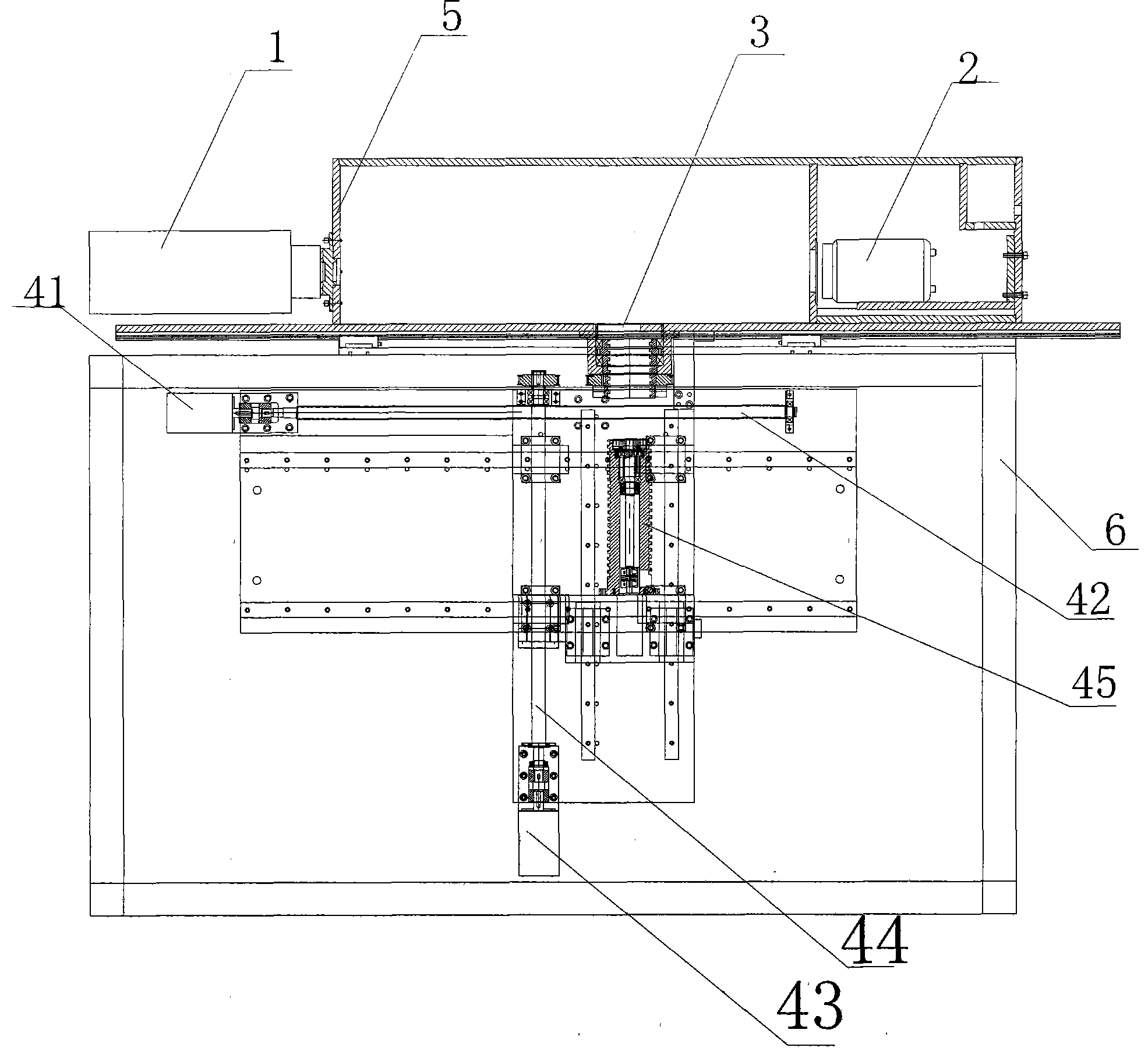
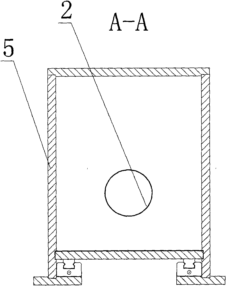
[0037] Embodiments are shown in Figures 1 to 5, the micro-CT imaging device with three-degree-of-freedom motion control includes an X-ray source 1, an X-ray detector 2, and a sealed box 5 for installing the X-ray source and X-ray detection The sealing box of the device, the system skeleton, the cabinet door, the safety shielding device, the external frame, etc.; the stage 3 is set between the X-ray source 1 and the X-ray detector 2, and the drive stage is set on the outside of the stage. Driving device for horizontal, vertical and rotational movement. The X-ray detector 2 is arranged in the sealed box, and forms a closed chamber with the X-ray source 1 an...


PUM


Abstract

The invention provides a microscopy CT imaging device with three-free degree motion control and a correcting method thereof. The microscopy CT imaging device comprises an X-ray source (1) and an X-ray source detector (2), wherein a material-carrying table (3) is arranged between the X-ray source (1) and the X-ray source detector (2). The device is characterized in that the material-carrying table is externally provided with a driving device for driving the material-carrying table to move along the horizontal direction, the vertical direction and the rotation direction. The device solves the problems of serious shake, large error and low precision when the common microscopy CT mechanical device moves; leads the three-free degree direction motion to be more stable, the speed to be more even, and the precision degree to be higher; has better radiation shield effect; solves the problem of the heat dissipation of the X-ray source and the X-ray source detector; solves the problem that the X-ray source, the X-ray source detector and a material-rotating center are positioned at one line; and lays good foundations for the subsequent image acquisition and image reconstruction.

Description

technical field [0001] The invention belongs to the technical field of micro-X-ray computed tomography imaging, in particular to a three-degree-of-freedom control system of micro-CT imaging equipment. Background technique [0002] X-ray computed tomography (x-ray computedtomography, x-ray CT or CT) appeared in the 1970s, which is the product of the combination of modern computer technology and X-ray inspection technology. In 1971, British EMI company Hounsfield successfully developed the first head CT scanner. In 1975, the first full-body CT machine designed by Ledkey in the United States came out. It used X-ray beams to scan the human body, obtain information, and obtain reconstructed images through computer processing. , thereby significantly expanding the scope of human body inspection, improving the detection rate of lesions and the accuracy of diagnosis. This diagnostic method with high diagnostic value, no pain, no trauma, and no danger is a major breakthrough in the ...

Claims


Application Information

Patent Timeline
IPC IPC(8): G01N23/04A61B6/03G05D3/00
Inventor 陈功罗守华张勇董歌张奎
Owner 苏州和君科技发展有限公司
Learn More