Manufacturing method of heat pipe

A manufacturing method and technology of heat pipes, which are applied to tubular elements, heat exchange equipment, indirect heat exchangers, etc., can solve problems such as unfavorable observation and monitoring of heat pipes, opaque shells, etc., and achieve the effect of enhancing excellent heat transfer performance.

Inactive Publication Date: 2013-01-23
FURUI PRECISE COMPONENT (KUNSHAN) CO LTD +1
View PDF0 Cites 0 Cited by
  • Summary
  • Abstract
  • Description
  • Claims
  • Application Information

AI Technical Summary

Problems solved by technology

[0003] The shell of the heat pipe is usually made of metal materials with high thermal conductivity, such as copper, aluminum, etc., the shell is opaque, and the working process of the working fluid inside it cannot be directly observed visually, but can only be obtained theoretically. It is not conducive to real-time observation and monitoring of the working status of the heat pipe.

Method used


Image

  • Manufacturing method of heat pipe
  • Manufacturing method of heat pipe
  • Manufacturing method of heat pipe

Examples


Embodiment Construction

[0010] The present invention will be further described below in conjunction with the embodiments with reference to the accompanying drawings.

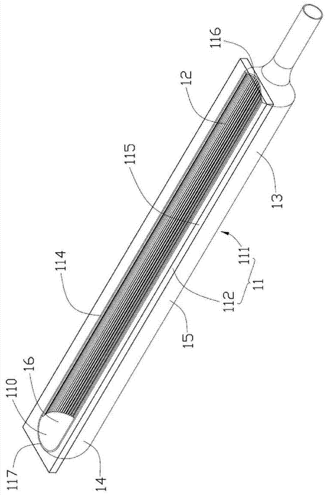
[0011] Normally, the heat pipe generally includes a sealed shell in which a working fluid is encapsulated and capillary structures are provided on the inner wall or cavity of the shell. The overall shape of the heat pipe mainly has a plate shape (flat shape) or a tube shape. In this embodiment, a tube heat pipe is taken as an example for illustration, but the present invention is not limited to the scope of the tube heat pipe.

[0012] Such as figure 1 As shown, the heat pipe 10 includes a closed casing 11 , a capillary structure 12 disposed in the casing 11 , and an appropriate amount of working fluid (not shown) filled in the casing 11 . The heat pipe 10 includes an evaporating section 13 and a condensing section 14 respectively located at two ends of the housing 11 , and an adiabatic section 15 connected between the evaporating sec...


PUM


Abstract

A heat pipe includes a sealed hollow casing, a wick structure lining an inner surface of the casing and a working medium contained in an interior of the casing. The casing includes an elongated main body having an elongated opening extending axially in the main body and a transparent cover fixed onto the main body and sealing the opening of the main body. The wick structure is provided by only lining an inner surface of the main body of the casing.

Description

technical field [0001] The invention relates to a heat pipe, in particular to a heat pipe whose working state of the internal working fluid can be visualized and its manufacturing method. Background technique [0002] At present, heat pipes have been widely used in the heat dissipation of electronic components with large heat generation. The heat pipe usually includes a shell, a capillary structure attached to the inner surface of the shell, and a working fluid with a low boiling point filled in the shell. The housing includes an evaporation section and a condensation section located at opposite ends. When working, the heat pipe uses the internal working fluid of the shell to absorb the heat generated by the heating electronic components in the evaporation section, then evaporates and vaporizes, moves to the condensation section with heat, and releases the heat through liquefaction and condensation in the condensation section. The liquefied work Under the action of the cap...

Claims


Application Information

Patent Timeline
Patent Type & Authority Patents(China)
IPC IPC(8): F28D15/04
CPCF28F2255/00H01L23/467F28D15/046F28F2220/00F28F1/24F28D15/0233H01L23/427H01L2924/0002Y10T29/49353H01L2924/00
Inventor 谢宜莳王永健
Owner FURUI PRECISE COMPONENT (KUNSHAN) CO LTD
Why Eureka
Try Eureka