
Circulation evaporator

An evaporation device and evaporation liquid technology, applied in the field of evaporation system, can solve the problems of no obvious improvement in energy saving effect, large number of system equipment, complex control system, etc., to meet the needs of production process, control links and investment, The effect of low evaporation temperature

Inactive Publication Date: 2010-08-25
兰州节能环保工程有限责任公司 +1
View PDF5 Cites 23 Cited by
  • Summary
  • Abstract
  • Description
  • Claims
  • Application Information

AI Technical Summary

Problems solved by technology

[0003] Theoretically, the more effective evaporators used in traditional evaporation systems, the higher the heat energy utilization rate. Therefore, in order to reduce energy consumption and improve heat energy utilization efficiency in traditional evaporation systems, in most cases, a combination of multi-effect evaporators is used. , which will make the whole system a large number of equipment, occupy more space, and complicate the control system
In the multi-effect evaporator system, when the number of evaporator effects increases to a certain level, due to the decrease in effective temperature difference, the temperature loss increases, and the evaporation intensity decreases. Every time an additional effect evaporator is added, a huge investment in equipment is required, but the energy-saving effect is low. There is no obvious improvement, so at present, the evaporator efficiency of the evaporation system is basically between five and seven effects, and the goal of further improving energy utilization efficiency in the traditional evaporation system has fallen into a technical bottleneck

Method used


Image

  • Circulation evaporator
  • Circulation evaporator

Examples


Embodiment Construction

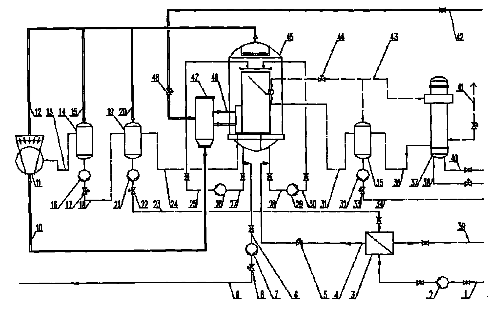
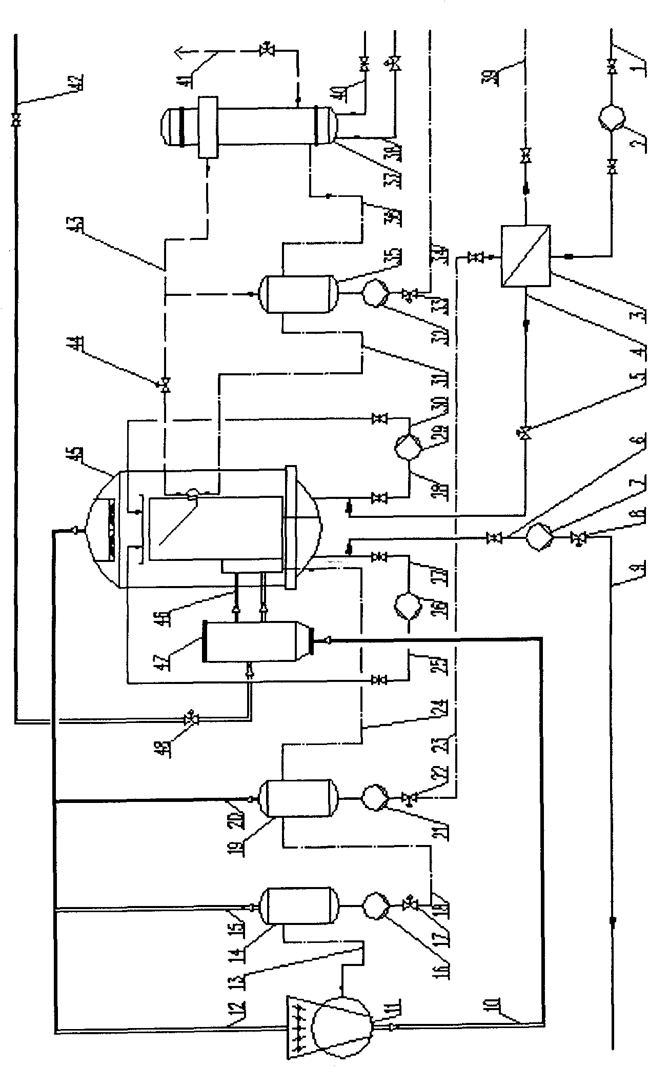
[0018] FIG. 1 is a schematic diagram of an embodiment of the device of the present invention, and FIG. 1 fully shows the composition of each component and the connection relationship with each other. A specific embodiment of the present invention is as follows: according to process requirements, first determine the specifications and technical parameters of main and auxiliary equipment such as falling film evaporator, heater, condenser, steam compressor, etc. Taking papermaking black liquor treatment as an example, if the total amount of dilute black liquor to be treated is 170M 3 / H, the initial temperature is 75°C, the solid content percentage concentration of the dilute black liquor is 1.5%, and the treated black liquor requires a solid content percentage concentration of 15%. By calculation, the area of ​​the falling film evaporator is 9500M 2 , the shell side working temperature is 95℃, the plate (or tube) side working temperature is 105℃; the heater area is 200M 2 , the...


PUM


Abstract

The invention discloses an evaporator for performing innocent treatment on sewage in industries of papermaking and the like. In an existing device, a secondary steam pipe is connected to an inlet of a compressor; an outlet of the compressor is connected with a steam inlet of a steady head tank; the other steam inlet pipe of the steady head tank is connected with a fresh steam pipe of a boiler; a steam outlet of the steady head tank is connected with a falling-film evaporator which is at least provided with one circulating pipe connected with a circulating pump; an outlet of a stripper plant of the falling-film evaporator is communicated with a non-condensable air pipe and a heavily-polluted condensate water outlet pipe which is communicated with a water inlet of a heavily-polluted condensate water tank; a water outlet of the heavily-polluted condensate water tank is communicated with a heavily-polluted condensate water delivery pipe; and a condensation water outlet pipe of a condenser is communicated with the water inlet of the heavily-polluted condensate water tank.

Description

technical field [0001] The invention relates to an evaporation system, especially an evaporation device used for harmless treatment of sewage in industries such as papermaking. It consists of steam pipe, secondary steam pipe, connecting pipes, valves and pumps. Background technique [0002] Evaporation system plays a very important role in modern industry, or realizes the evaporation and concentration of a certain solution, or realizes the extraction and separation of different products. It is widely used in papermaking, petrochemical, food and beverage processing and other fields, effectively reducing the evaporation system. It has great social significance and economic benefits. For traditional evaporation systems, in order to save operating costs, reduce energy consumption and achieve different process needs in the actual use process, multi-effect evaporation is often used, in which the I-effect evaporator uses the boiler fresh steam as the heating heat source. The seco...

Claims


Application Information

Patent Timeline
Patent Type & Authority Applications(China)
IPC IPC(8): C02F1/04
Inventor 张培洲邵珲张舒张兵
Owner 兰州节能环保工程有限责任公司
Learn More