Pneumatic tire

A technology for pneumatic tires and tires, applied in tire parts, tire tread/tread pattern, transportation and packaging, etc., can solve the problem of insufficient effect, inability to ensure tire block rigidity, and deterioration of braking performance on icy and snowy roads and other problems, to achieve the effect of suppressing the ground area and suppressing the reduction

Inactive Publication Date: 2010-08-25
TOYO TIRE & RUBBER CO LTD
View PDF10 Cites 1 Cited by
  • Summary
  • Abstract
  • Description
  • Claims
  • Application Information

AI Technical Summary

Problems solved by technology

However, none of these pneumatic tires can secure sufficient rigidity of the entire block, and the effect of suppressing sipe collapse is not sufficient, so there is a tendency for the braking performance on ice and snow roads and the braking performance on dry roads to deteriorate.

Method used


Image

  • Pneumatic tire
  • Pneumatic tire
  • Pneumatic tire

Examples


Embodiment approach

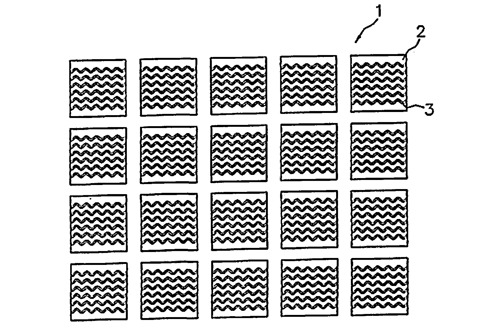
[0039] (1) In the above-mentioned embodiment, an example of a pneumatic tire having blocks 2 in which a plurality of sipes 3 are formed on the tread 1 is shown. In the present invention, it may be a pneumatic tire having a rib as a land portion, A pneumatic tire in which sipes 3 are formed on the ribs.

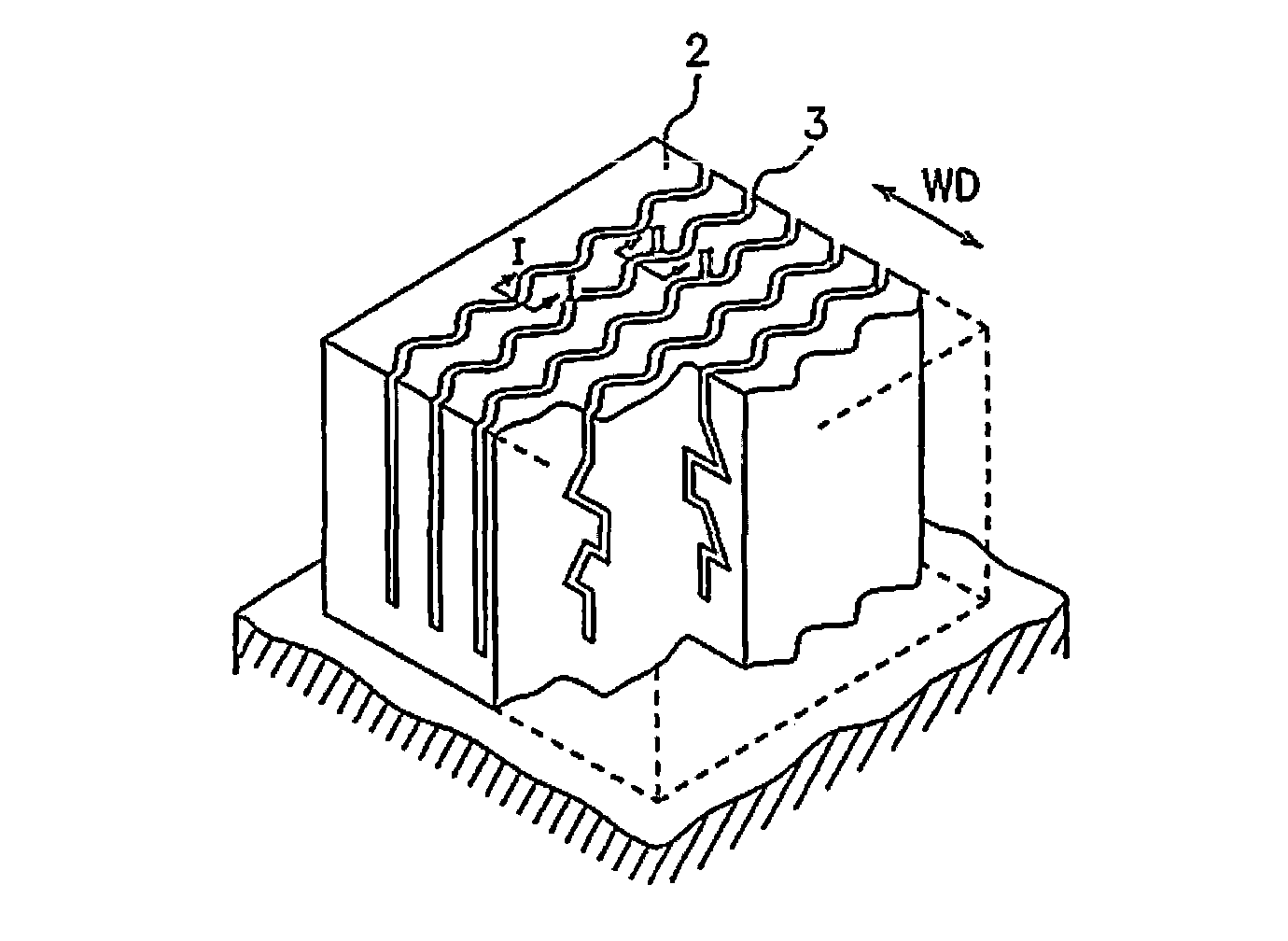
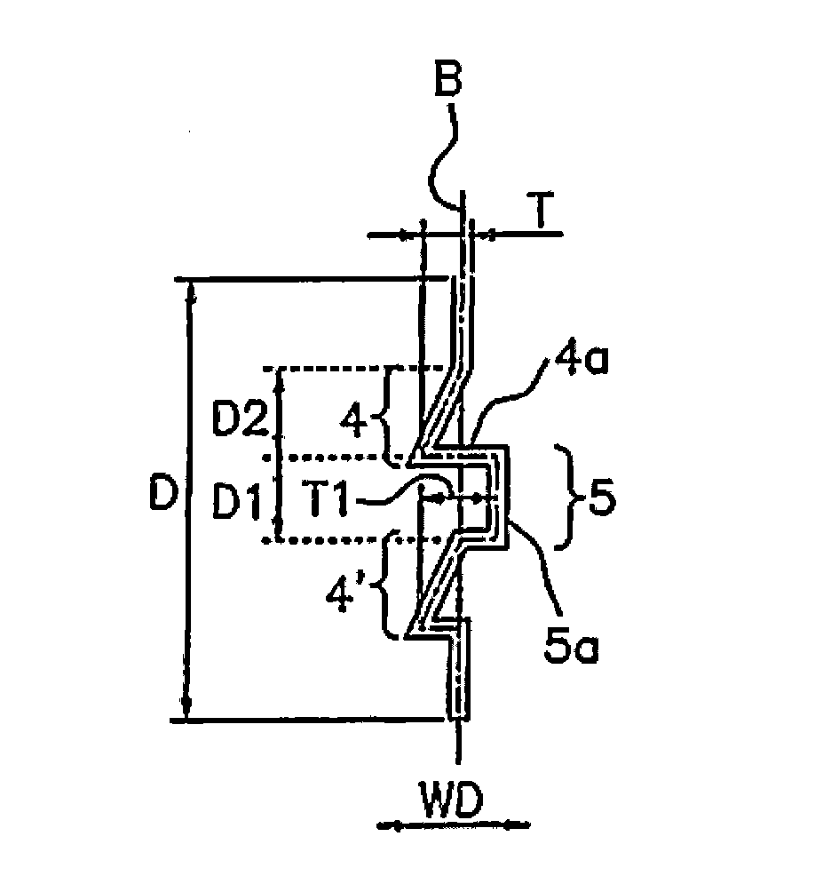
[0040] (2) In the above-mentioned embodiment, there is shown the concave portion 4 with a concave longitudinal section and the convex portion 5 with a convex longitudinal section on the outer top and the inner top with respect to the reference plane B from the side close to the tread of the block 2 . Sipe 3 example. However, in the present invention, if Figure 5 As shown in (a), even if the sipe 3 has only the convex portion 5, the engaging force in the depth direction of the sipe can be sufficiently increased, and the suppressing effect is hardly affected by the collapse direction of the sipe 3. Therefore, even when the sipe 3 has only the convex portion 5 , it is possible...

Embodiment 1

[0051] exist figure 1 In the tread pattern shown, the formation Figure 2 ~ Figure 4 For the sipes 3 of the shape shown, the sipes 3 are manufactured with a sipe width of 0.3 mm, a sipe depth D of 7 mm, a half-length T of the amplitude of the wavy line on the surface of the block 2 of 0.7 mm, and a concave portion A pneumatic tire in which the maximum sipe width direction length T1 of the flat surface 4 a of 4 is 1.4 mm, the sipe depth direction length D1 of the convex portion 5 is 1.3 mm, and the sipe depth direction length D2 of the concave portion 4 is 1.3 mm. Using this tire, the performance evaluations described above were performed, and the results are shown in Table 1.


PUM


Abstract

An object of the present invention is to provide a pneumatic tire that ensures both of the on-ice braking performance and the dry braking performance. In order to achieve the object, a pneumatic tire comprises a tread surface (1) including a land portion in which a plurality of sipes (3) are formed, wherein each of the sipes (3) includes a reference plane (B) extending in a depth direction of the sipe from a wavy or zigzag line in the surface of the land portion and each of the sipes is formed with a convex portion having a convex shape in a vertical section with respect to the reference plane (B) in a top area at the front side and the rear side thereof. Preferably each of the sipes (3) is further formed with a concave portion (4) having a concave shape in the vertical section with respect to the reference plane in a top area at the front side and the rear side thereof. The concave portion (4) includes a flat plane portion located at the convex portion (5) side as viewed in the depth direction of the sipe extending in the width direction (WD) of the sipe, and the convex portion is connected to the flat plane portion (4a).

Description

technical field [0001] The present invention relates to a pneumatic tire having a ground portion with a plurality of sipes formed on the tread surface, which is particularly suitable for use as a studless antiskid tire for passenger cars. Background technique [0002] Conventionally, in studless tires for passenger cars, for the purpose of improving the driving performance on ice and snow roads with a low coefficient of friction (hereinafter referred to as "ice and snow performance"), it is known that each part of the tire tread ( An example in which a plurality of sipes are arranged in the center portion, the connecting portion, and the shoulder portion). Furthermore, for the purpose of improving the braking performance on ice and snow (hereinafter referred to as "ice and snow braking performance"), a plurality of sipes extending in the tire width direction are arranged to improve the edge effect in the front and rear directions. Forming such sipes in the land portion impr...

Claims


Application Information

Patent Timeline
Patent Type & Authority Applications(China)
IPC IPC(8): B60C11/12
CPCB60C2011/1213B60C11/12B60C11/1218
Inventor 大桥稔之宫崎哲二
Owner TOYO TIRE & RUBBER CO LTD
Why Eureka
Try Eureka