Pneumatic tire with tread having long hole shaped depressions

Active Publication Date: 2014-11-04
TOYO TIRE & RUBBER CO LTD
View PDF25 Cites 0 Cited by
  • Summary
  • Abstract
  • Description
  • Claims
  • Application Information

AI Technical Summary

Benefits of technology

This invention is about a pneumatic tire that reduces irregular wear on the tread surface. The invention includes a depression row on the first edge of the land portion, which reduces the ground area and increases the ground pressure to accelerate wear speed. The second edge of the land portion does not have the depression row, so the wear speed between the first and second edges is balanced, reducing the difference in wear between the two edges. The depression has a long hole shape, which also increases the ground pressure. Three or more main grooves on the tread surface can also contribute to irregular wear. The depression is preferably located on the outermost side or near the tire equator, and the depth of the depression is preferably between 0.20 and 0.70 to achieve uniform wear and excellent performance. A reinforcing portion can be included to increase rigidity of the first edge portion and prevent wear speed from becoming too fast.

Problems solved by technology

If three or more main grooves are formed on the tread surface, a center wear or a shoulder wear tends to be generated in the land portion separated into a center side and a shoulder side.

Method used


Image

  • Pneumatic tire with tread having long hole shaped depressions
  • Pneumatic tire with tread having long hole shaped depressions
  • Pneumatic tire with tread having long hole shaped depressions

Examples


examples

[0044]An example tire which concretely shows the structure and effect of the present invention will be explained. In this case, an evaluation of each of performances of a tire is executed as follows.

[0045](1) Irregular Wear Resistance (Irregular Wear Ratio)

[0046]A test tire (a tire size: LT265 / 75R16) is installed as a rear tire to a diesel truck (6600 cc, 4WD), an air pressure is set to 520 kPa, and an irregular wear ratio (wear amount in a center side main groove / wear amount in a shoulder side main groove) is calculated after traveling 20000 km on a general road. An irregular wear ratio closer to 1 indicates a wear closer to a uniform wear, that is, an excellent irregular wear resistance.

[0047](2) Drainage Performance

[0048]A test tire (a tire size: LT265 / 75R16) is installed as a rear tire to a diesel truck (6600 cc, 4WD), an air pressure is set to 520 kPa, an air pressure of a front tire is set to 420 kPa, and a speed at a time when a hydroplaning phenomenon is generated during tra...

examples 1 and 2

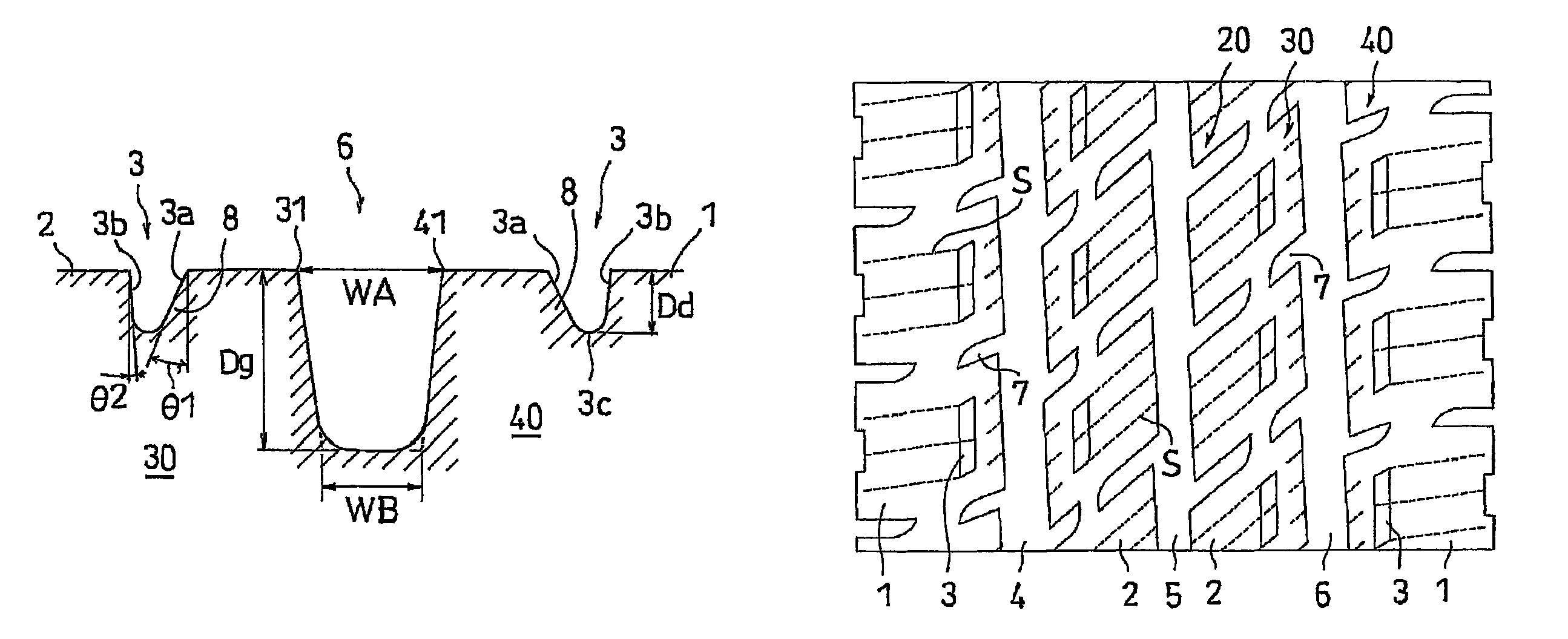
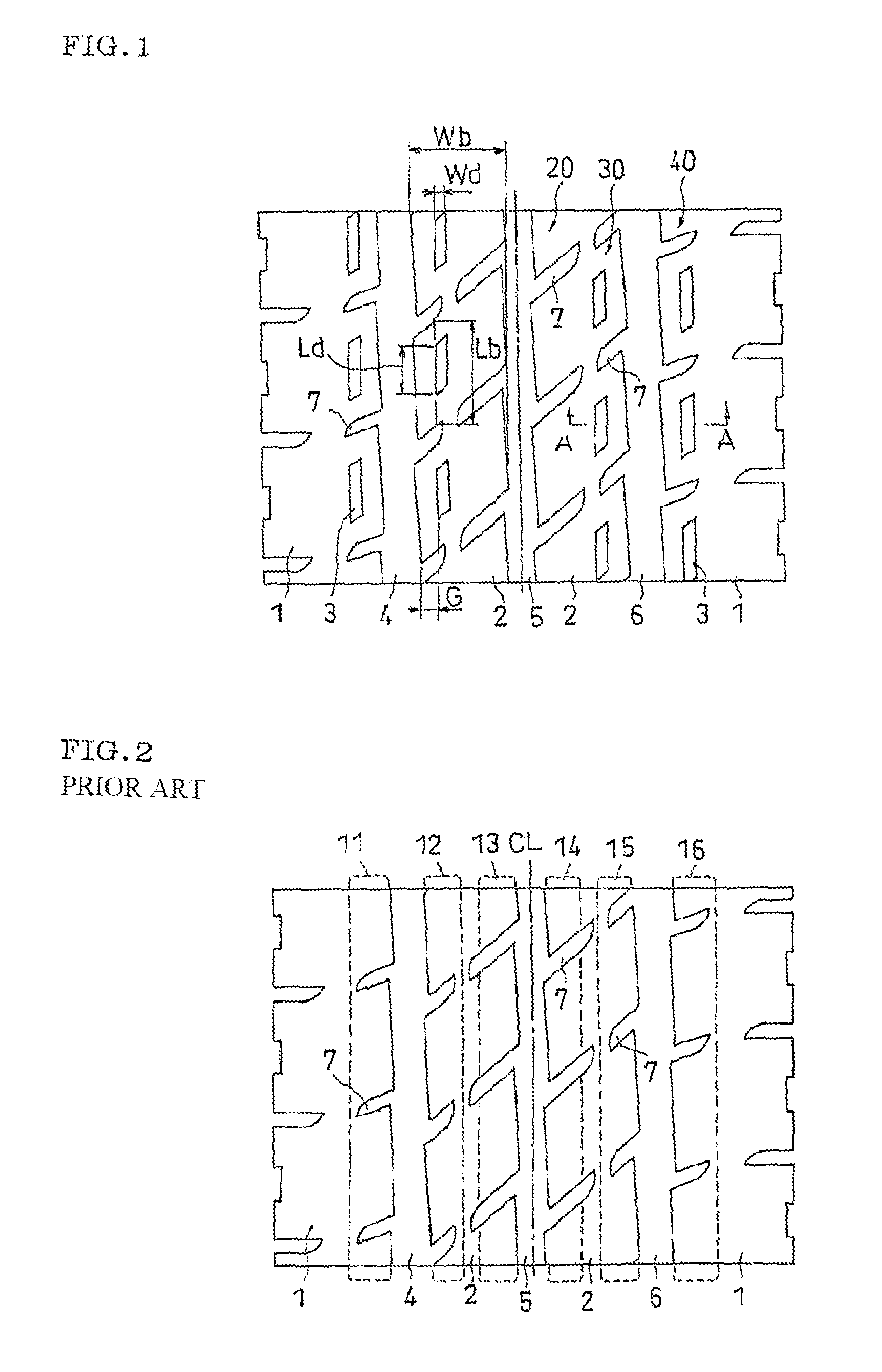
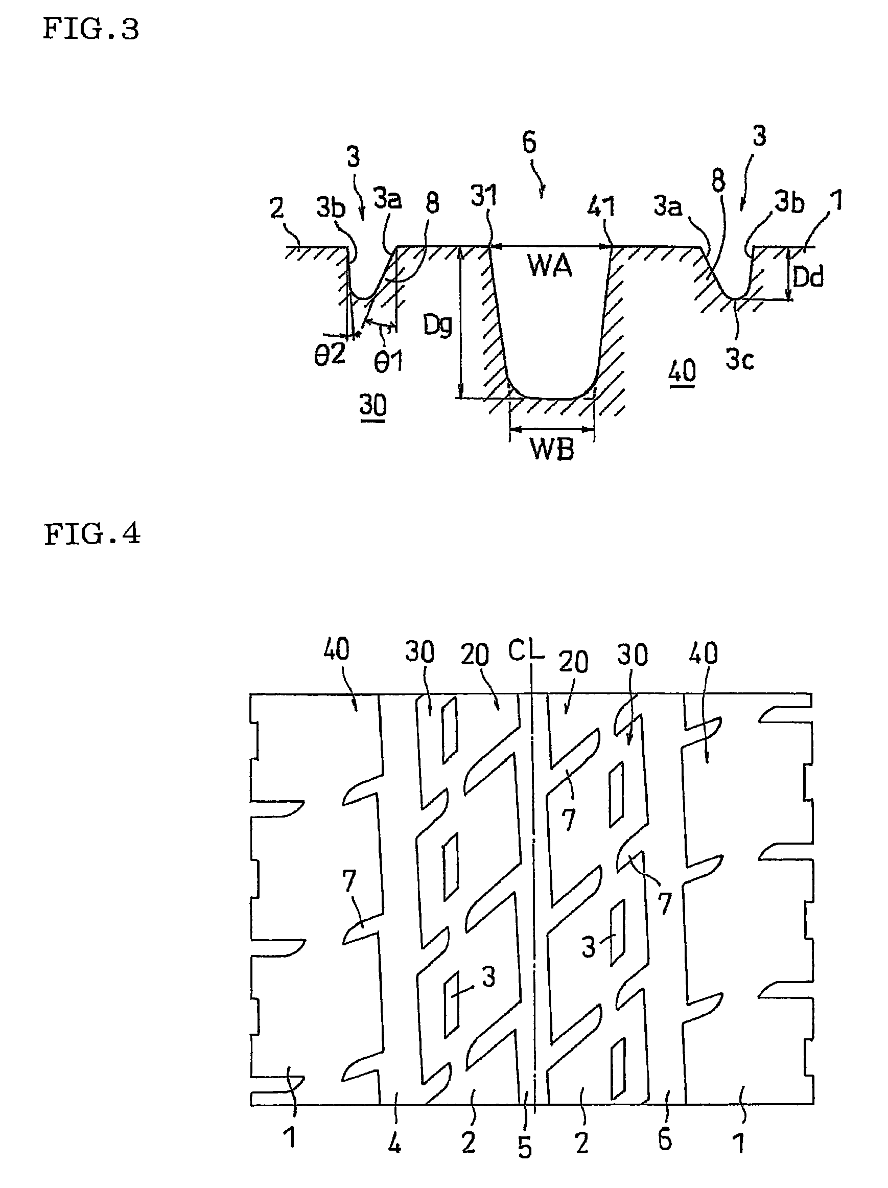
[0050]An example 1 is set to a structure in which the center side main groove is formed in a U-shaped cross section and groove wall angles θ1 and θ2 of the depression are both 0 degree, in the tread surface shown in FIG. 1, and an example 2 is set to a structure in which a reinforcing portion is provided in the depression by setting the groove wall angle θ1 to 10 degree in the same manner. In this case, the depth Dg of the main groove is set to 12.5 mm, a ratio Dd / Dg of the depth of the depression with respect to the main groove is set to 0.40, a ratio Wd / Wb of the width with respect to the block is set to 0.11, a distance G in the tire width direction from the edge end is set to 9 mm, and a ratio Ld / Lb of the length with respect to the block is set to 0.50. Results of the evaluation are shown in Table 1.

[0051]

TABLE 1Ir-Shape ofregularmainDepres-ReinforcingwearDrainagegroove 5sionportionratioperformanceComparativeU-shapedNoneNone2.5100Example 1crosssectionComparativeV-shapedNoneNone...


PUM


Abstract

In the invention, a tread surface is provided with a groove portion including a main groove continuously extending in a tire circumferential direction, and a land portion including a rib or a block separated by the main groove, wherein the land portion includes a first edge portion having a depression row formed by arranging long hole shaped depressions extending along the groove portion in the tire circumferential direction and a second edge portion extending along the main groove while being different in position in a tire width direction from the first edge portion, and not having the depression row.

Description

BACKGROUND OF THE INVENTION[0001]1. Field of the Invention[0002]The present invention relates to a pneumatic tire in which a tread surface is provided with a groove portion including a main groove continuously extending in a tire circumferential direction, and a land portion including a rib or a block separated by the main groove.[0003]2. Description of the Related Art[0004]Conventionally, various ideas have been cast around in connection with a problem of an irregular wear generated on a tread surface. As the irregular wear mentioned above, there has been known, for example, a center wear in which a center region of the tread surface is worn in a comparatively early stage, and a shoulder wear in which a shoulder region is worn in a comparatively early stage. As a generation cause thereof, there can be listed up an uneven ground pressure balance of the tread surface based on a tread pattern and a tire shape. In other words, in the case where the ground pressures are greatly differen...

Claims


Application Information

Patent Timeline
IPC IPC(8): B60C11/117B60C11/03
CPCB60C11/032B60C11/0309B60C2011/0381B60C11/0306Y10S152/03
Inventor MIYAZAKI, TETSUJI
Owner TOYO TIRE & RUBBER CO LTD
Why Eureka
Try Eureka