
Measuring device during machining of cylindrical grinder

A technology for measuring devices and cylindrical grinding machines, which is applied to metal processing equipment, parts of grinding machine tools, manufacturing tools, etc., can solve problems such as poor stability, inconvenience, and inconvenient measurement, and achieve good stability and convenient adjustment. Effect

Inactive Publication Date: 2010-08-18
苏秀章
View PDF6 Cites 6 Cited by
  • Summary
  • Abstract
  • Description
  • Claims
  • Application Information

AI Technical Summary

Problems solved by technology

[0002] In the current cylindrical machining process, especially in the cylindrical grinding process, in order to ensure the required high precision, repeated measurements are required. For small-diameter external circles, measuring tools can be used to directly clamp the external circle for measurement. Although it is convenient, it cannot guarantee the accuracy of the measurement. For the outer circle with a large diameter, it is inconvenient to directly clamp the outer circle with a measuring tool. The uniformity and stability of the workpiece size increases the scrap rate and labor intensity
[0003] The Chinese utility model patent with the current notification number CN201203398 disclosed a comprehensive measuring instrument for the outer diameter of the piston on March 4, 2009. This utility model solves the problems of low precision and poor stability of the current measuring device. Its structure is as follows: it includes a bottom plate, and a positioning block is arranged on both sides of one end of the bottom plate, and a fixed vertical plate is installed by positioning the positioning block, and a measuring vertical plate composed of a large measuring vertical plate and a small measuring vertical plate is installed on the opposite side of the fixed vertical plate. The measuring vertical plate is connected with the adjustment device; the measuring flat plate is installed between the fixed vertical plate and the measuring vertical plate, and the side head device is installed on both the fixed vertical plate and the measuring vertical plate; the sensor frame is installed on the bottom plate on one side of the measuring vertical plate, The dial indicator and the dial indicator are installed on the sensor frame; the dial indicator and the small measuring vertical plate, and between the dial indicator and the large measuring vertical plate are slid and fitted through the adjustment device to obtain the measured value
Although this structure solves the problem of high measurement accuracy, the structure is complex and it is inconvenient to measure the outer circle during processing. Therefore, it is necessary to provide a simple structure, convenient measurement, high precision, and reduce scrap rate and labor. In-process measuring device for strength on cylindrical grinder

Method used


Image

  • Measuring device during machining of cylindrical grinder
  • Measuring device during machining of cylindrical grinder

Examples


Embodiment Construction

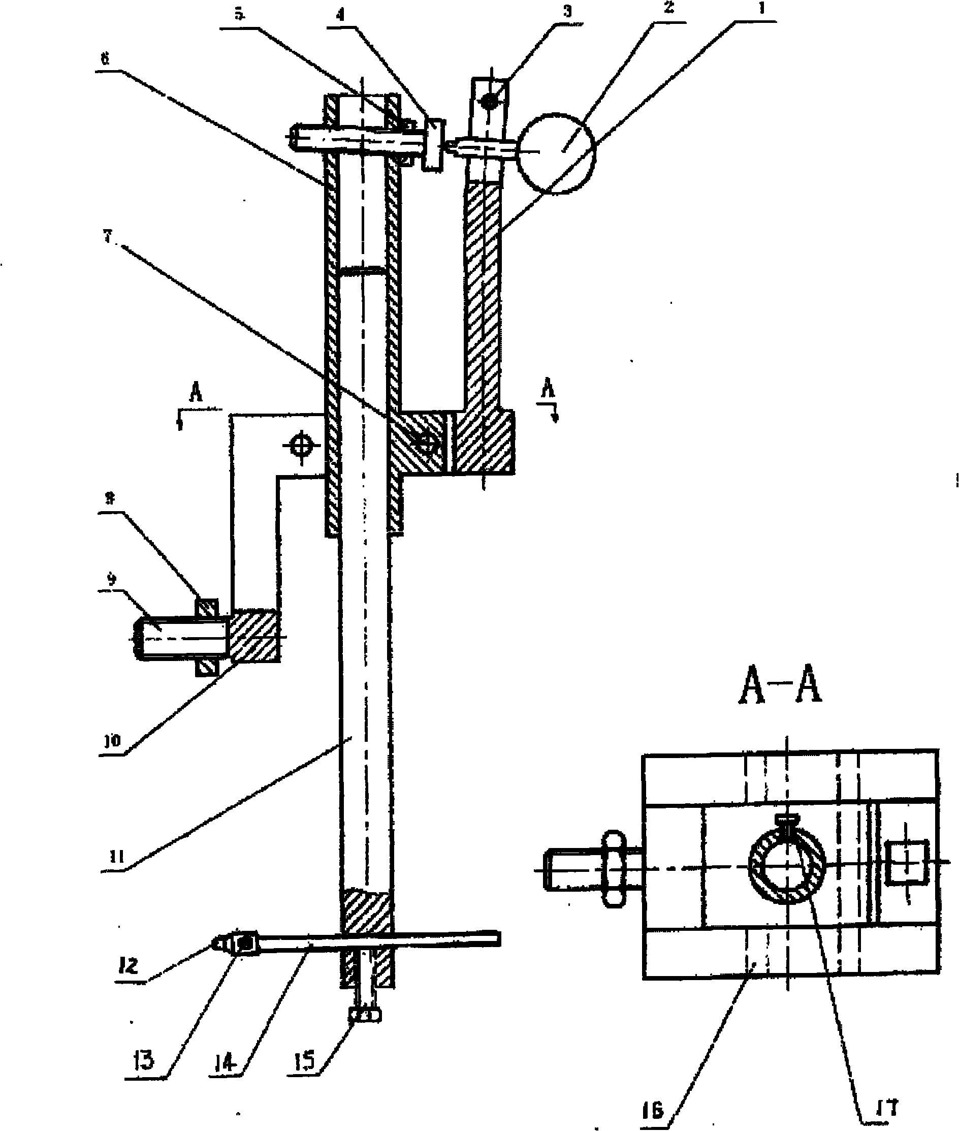
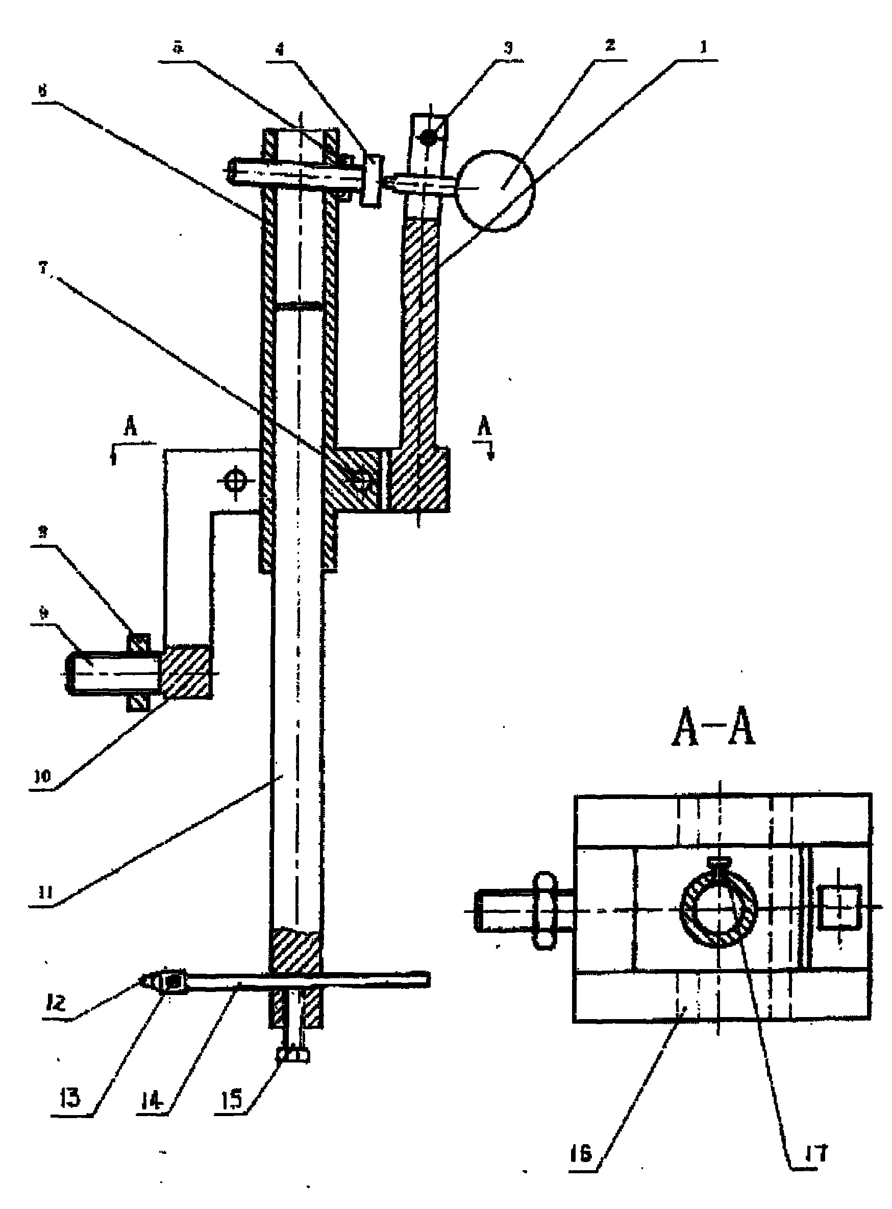
[0018] Such as figure 1 Shown: a cylindrical grinding machine processing measuring device, including a measuring device main body 10, a measuring rod movable sleeve 6, a measuring rod 11, a dial indicator 2, a measuring head 12, and an adjustment device, etc., a total of 17 parts. The specific embodiment is that the dial indicator 2 is vertically fixed on the dial indicator fixing rod 1 of the main body of the measuring device through the fastening screw 3, the dial indicator adjustment rod 4 is fixed at the end of the measuring rod movable sleeve 6 through the lock nut 5, and the measuring rod moves The cover 6 is installed on the middle and upper part of the main body 10 of the measuring device by means of the pin shaft 7, and the measuring rod 11 is housed in the movable cover 6 of the measuring rod, which is locked and fixed by the locking nut 17. The lower part of the main body of the measuring device is equipped with a brake pin 16, and the front end of the measuring rod...


PUM


Abstract

The invention discloses a measuring device during the machining of a cylindrical grinder, which comprises a measurement main body, a measuring head, an adjusting device of the measuring head, a dial gauge and an adjusting device of the dial gauge. The device comprises the key points that: the dial gauge is vertically arranged on a dial gauge fixing rod of the main body through locking screws; the dial gauge adjusting rod is fixed at the tail end of a movable sleeve of a measuring rod through clamp nuts to keep concentric with the center line of the dial gauge; the movable sleeve of the measuring rod is arranged on the upper part of the measurement main body through a pin shaft; the measuring rod is fixedly arranged in the movable sleeve of the measuring rod through the locking screws; the measuring rod is integrated with the movable sleeve to move up and down by taking the pin shaft as the centre of a circle; a measuring head up-down adjusting arm fixed on the measuring rod through clamp screws is inserted into the lower end of the measuring rod; the measuring head is fixed at the lower end of the adjusting arm through the locking screws; and the whole measuring device is fixedly arranged at the corresponding position of a machine body through main body fixing screws. The measuring device has the advantages of simple structure, convenient measurement, high precision, scrap rate reduction and labor intensity reduction.

Description

technical field [0001] The invention relates to a measuring device, in particular to a measuring device for dimension tolerance, shape tolerance, etc. of workpieces in the processing of cylindrical grinding machines. Background technique [0002] In the current cylindrical machining process, especially in the cylindrical grinding process, in order to ensure the required high precision, repeated measurements are required. For small-diameter external circles, measuring tools can be used to directly clamp the external circle for measurement. Although it is convenient, it cannot guarantee the accuracy of the measurement. For the outer circle with a large diameter, it is inconvenient to directly clamp the outer circle with a measuring tool. The uniformity and stability of the workpiece size increases the scrap rate and labor intensity. [0003] The Chinese utility model patent with the current notification number CN201203398 disclosed a comprehensive measuring instrument for the...

Claims


Application Information

Patent Timeline
Patent Type & Authority Applications(China)
IPC IPC(8): B24B49/04
Inventor 苏秀章
Owner 苏秀章
Learn More