Fuel cell system, and electronic device
A fuel cell system and fuel technology, applied in the direction of fuel cells, fuel cell additives, fuel cell components, etc., can solve problems such as output reduction and instability, and achieve high output, high power consumption, and multi-functional performance Effect
- Summary
- Abstract
- Description
- Claims
- Application Information
AI Technical Summary
Problems solved by technology
Method used
Image
Examples
no. 1 approach
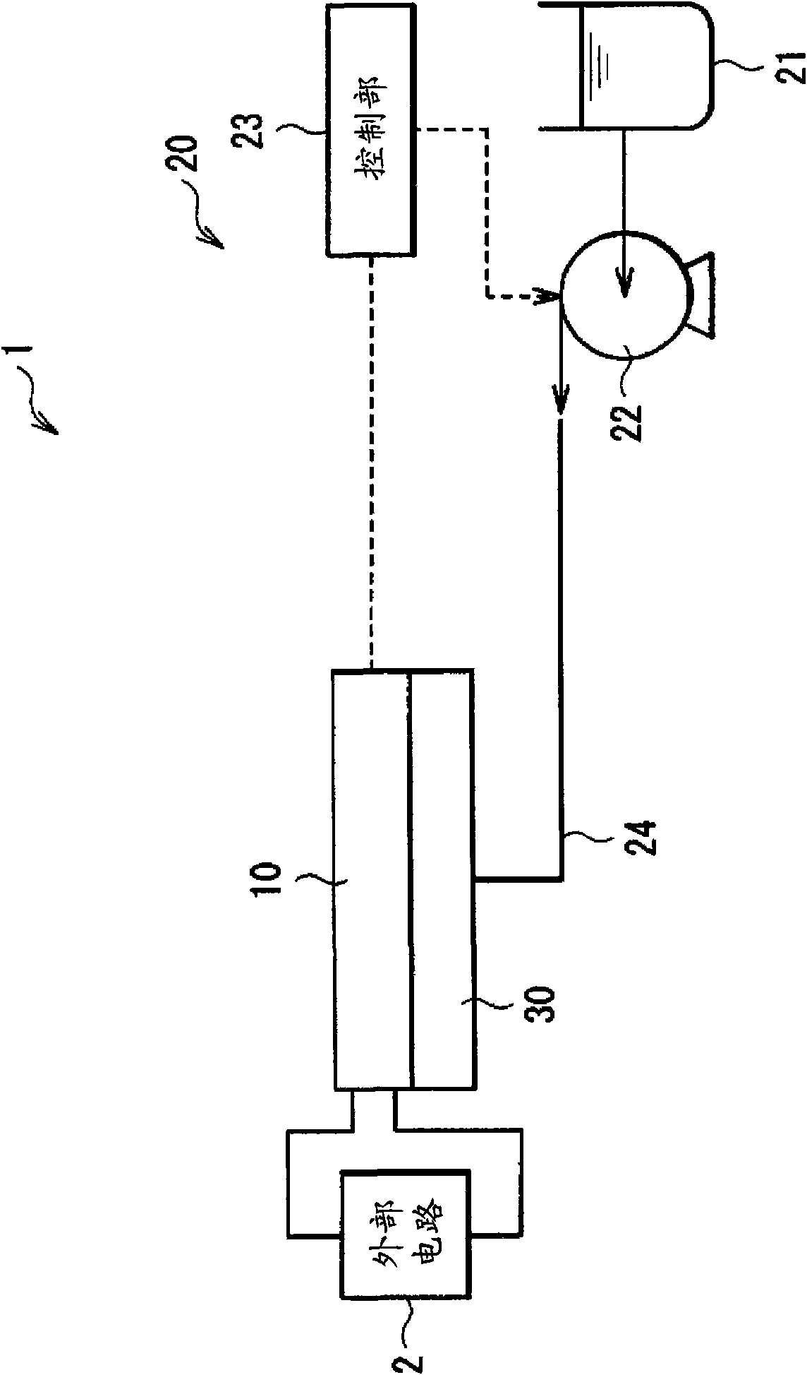
[0053] figure 1 A schematic structure of an electronic device having the fuel cell system according to the first embodiment of the present invention is shown. The electronic device is, for example, an electronic device such as a mobile phone and a notebook PC (Personal Computer). The electronic device includes a fuel cell system 1 and an external circuit (load) 2 driven by electric energy generated by the fuel cell system 1 . For example, the fuel cell system 1 includes a power generation unit 10 , a fuel supply control unit 20 , and a fuel vaporization unit 30 .
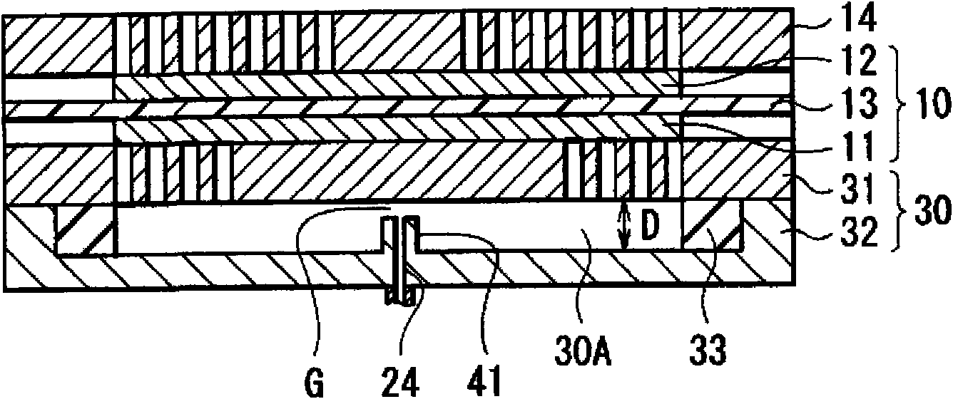
[0054] figure 2 One example of the power generation section 10 and the fuel vaporization section 30 is shown. For example, the power generation unit 10 is a DMFC including an electrolyte membrane 13 interposed between an anode 11 and a cathode 12 . The anode 11 and the cathode 12 have a structure in which a catalyst layer containing platinum (Pt), ruthenium (Ru) or the like is formed on the surface of carbon cl...
no. 2 approach
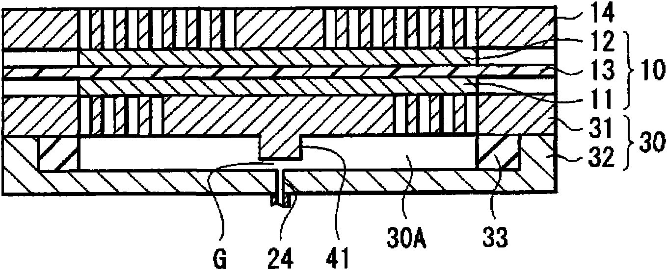
[0079] Figure 4 with Figure 5 The structures of the power generation section 10 and the fuel gasification section 30 according to the second embodiment of the present invention are shown. This embodiment has the same structure as the above-mentioned first embodiment except that the end of the protrusion 41 is in contact with Figure 4 The inner wall surface of the outer member 32 is in contact with the protrusion 41 and the Figure 5 The inner wall surface of the inner member 31 is in contact, and this embodiment can be manufactured in the same manner as the first embodiment described above.
[0080] The protrusion 41 is in contact with the inner wall surface of the outer member 32 or a portion on the inner wall surface of the inner member 31 adjacent to the end of the fuel supply passage 24 . Therefore, in this embodiment, the heat of the power generation part 10 is conducted to the outer member 32 or the inner member 31 through the protrusion 41 . Heat is conducted to ...
no. 3 approach
[0082] Image 6 The structures of the power generation section 10 and the fuel gasification section 30 according to the third embodiment of the present invention are shown. In this embodiment, a diffuser plate 50 that diffuses the liquid fuel supplied to the vaporization chamber 30A is provided on the inner wall surface of the outer member 32 . Therefore, in this embodiment, the liquid fuel supplied from the fuel supply passage 24 is diffused in the planar direction by the diffusion layer 50, and the fuel can be vaporized more efficiently and uniformly.
[0083] The diffuser plate 50 is made of resin such as porous polyethylene and porous polypropylene. The diffuser plate 50 is provided at or near the outlet of the fuel supply passage 24 . Ends of the protrusions 41 may be in contact with the diffuser plate 50 . In addition, a gap G may be provided between the end of the protrusion 41 and the diffuser plate 50 .
PUM
 Abstract
Description
Claims
Application Information
 - R&D
- Intellectual Property
- Life Sciences
- Materials
- Tech Scout
- Unparalleled Data Quality
- Higher Quality Content
- 60% Fewer Hallucinations
Browse by: Latest US Patents, China's latest patents, Technical Efficacy Thesaurus, Application Domain, Technology Topic, Popular Technical Reports.
© 2025 PatSnap. All rights reserved.Legal|Privacy policy|Modern Slavery Act Transparency Statement|Sitemap|About US| Contact US: help@patsnap.com


