
Flat-angle chip aslant sticking type back-off packaged electronic tag

A technology of electronic tags and chips, which is applied in the direction of circuits, seals, electrical components, etc., can solve the problems of diagonal antenna loops, circuit short circuits, narrow use range, etc., to improve packaging fault tolerance, reduce research and development costs, and work performance reliable effect

Inactive Publication Date: 2010-08-11
上海中京电子标签集成技术有限公司
View PDF0 Cites 0 Cited by
  • Summary
  • Abstract
  • Description
  • Claims
  • Application Information

AI Technical Summary

Problems solved by technology

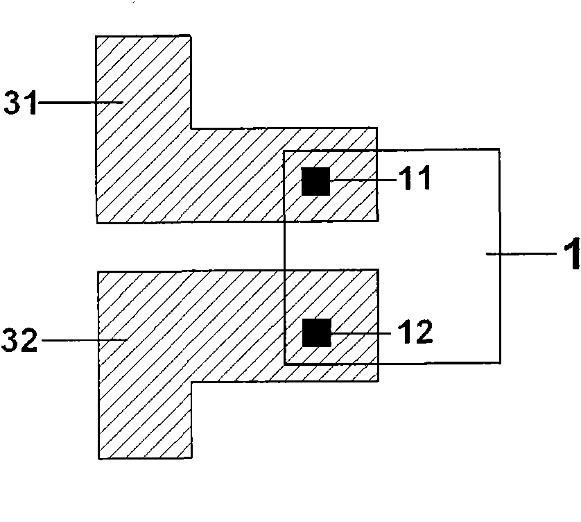
like Figure 3A-3D As shown, according to the horizontal upside-down packaging technology in the prior art, no matter how the flat-angle chip 1 is placed, it cannot form a loop with the diagonal antenna, so it cannot be used in conjunction with the diagonal antenna.
[0005] see Figure 4 , shown as a flat-angle chip 6 with a test point, the flat-angle chip 6 with a test point is provided with a test point 63 between the two binding points 61 and 62, when the test point 63 is in contact with the antenna coil, it will cause a circuit short circuit, burn bad electronic tag
[0006] In the prior art, when the flat-angle chip 6 with the test point is packaged on the flat-angle antenna by adopting the horizontal reverse packaging technology, since the distance between the two pins 31 and 32 is very small, the test point 63 reaches the two pins 31 and 32. The distance between them is very small, such as Figure 5 As shown, therefore, using the existing horizontal upside-down packaging technology, the packaging fault tolerance is low, resulting in a high probability of defective products, and the efficiency of the chip packaging process is low.
[0007] The disadvantage of chip upside-down packaging technology in the prior art is that the flat-angle chip can only be used in conjunction with the flat-angle antenna, and the scope of use is narrow. When you only have a diagonal antenna and a flat-angle chip in your hand, in order to make the two work together, you have to modify the antenna. pins or modify the setting method of the chip binding point, which increases the cost of research and development

Method used


Image

  • Flat-angle chip aslant sticking type back-off packaged electronic tag
  • Flat-angle chip aslant sticking type back-off packaged electronic tag
  • Flat-angle chip aslant sticking type back-off packaged electronic tag

Examples


Embodiment approach

[0036] see Figure 6 , an electronic label with a flat-angle chip obliquely attached to an upside-down package, including a flat-angle chip 1 and a diagonal antenna, one side of the flat-angle chip 1 is provided with two binding points 11 and 12 at intervals, and the flat-angle chip 1 is obliquely attached to the On the pins 41 and 42 of the diagonal antenna, the two binding points 11 and 12 of the flat-angle chip 1 are respectively connected to the two pins 41 and 42 of the diagonal antenna.

[0037] The diagonal antenna is arranged on the substrate 5, including an antenna coil 43, a riveting point 45 arranged at the first and last ends of the antenna coil 43, and a bridge line 44 connecting the first and last riveting points 45 of the antenna coil 43, the antenna coil The innermost part of 43 is disconnected, and the two ends of the disconnection respectively lead to the pins 41 and 42 connected to the flat-angle chip 1. The flat-angle chip 1 is packaged on the two pins thro...


PUM


Abstract

The invention relates to a flat-angle chip aslant sticking type back-off packaged electronic tag comprising a flat-angle chip and a diagonal antenna, wherein one side of the flat-angle chip is provided with two binding points at interval, the flat-angle chip is aslant stuck on the pins of the diagonal antenna, and the two binding points of the flat-angle chip are respectively connected with the two pins of the diagonal antenna. Because of adopting the aslant back-off packaging technology to pack the flat-angle chip, the flat-angle chip aslant sticking type back-off packaged electronic tag of the invention ensures that the flat-angle chip can be matched with the diagonal antenna so as to enlarge the using range of the flat-angle chip; and when the flat-angle chip is replaced, the original diagonal antenna does not need to redesign, so that the research cost is lowered.

Description

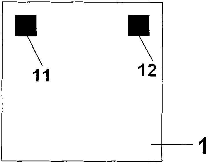
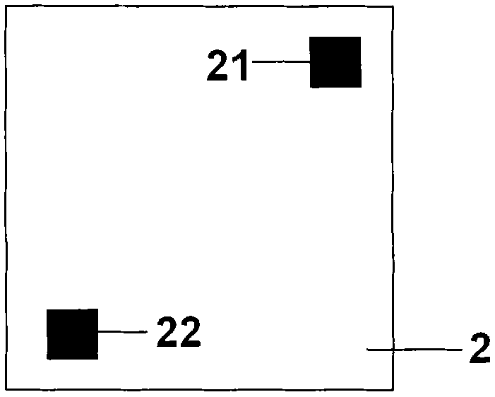
technical field [0001] The invention relates to an electronic label, in particular to an electronic label with a flat-angle chip obliquely pasted upside down and packaged. Background technique [0002] The electronic tag is composed of an antenna and a chip, and the chip is connected to the pin of the antenna through the binding point on it. In the prior art, there are two types of chips, one is a flat-angle chip, such as Figure 1A As shown, the feature of the flat-angle chip 1 is that the two binding points 11 and 12 on it are arranged on the same side, and another kind of diagonal chip, such as Figure 1B As shown, the diagonal chip 2 is characterized by two binding points 21 and 22 arranged on the diagonal. [0003] In the prior art, there are two pins of the antenna, which are respectively connected to a binding point of the chip, such as Figure 2A , 2B As shown, there are also two types of antenna pin settings, in Figure 2A Among them, the two pins 31 and 32 of t...

Claims


Application Information

Patent Timeline
Patent Type & Authority Applications(China)
IPC IPC(8): G09F3/02H01L23/48H01L23/64
Inventor 冀京秋王卿
Owner 上海中京电子标签集成技术有限公司
Learn More